T
ABLE
OF
C
ONTENTS
0 2 . 9 6 9 8 . 0 0 1 0 0
xv
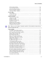
Strobe System Assembly ...................................................................................................... 104
Top Strobe Blade Assembly.................................................................................................. 106
Bottom Strobe Blade Assembly ............................................................................................ 107
Fixed Color Wheel 2 Assembly ............................................................................................ 108
Fixed Color Wheel 1 Assembly ............................................................................................ 110
Yoke Assembly ..................................................................................................................... 113
Tilt Motor Assembly ............................................................................................................. 115
Yoke Fan Assembly .............................................................................................................. 117
Upper Enclosure Assembly................................................................................................... 119
Stabilizer Assembly .............................................................................................................. 125
Pan Motor Assembly............................................................................................................. 126
Ventilation Cover Assembly ................................................................................................. 128
Input Panel Assembly ........................................................................................................... 129
Machined Pan Tube Assembly.............................................................................................. 130
High Flow Exhaust Fan Assembly........................................................................................ 131
Fan Regulator Board Assembly ............................................................................................ 132
Note:
Cables are only available as complete assemblies. The information contained in this
section is for reference only.
LVS Chassis Ground Cable Assembly.................................................................................. 133
Chassis To Yoke Ground Cable Assembly ........................................................................... 134
Head to Back Cap Ground Cable Assembly ......................................................................... 135
Ignitor to Relay Cable Assembly .......................................................................................... 136
Yoke Fan Cable Assembly .................................................................................................... 137
Data I/O Link Cable Assembly ............................................................................................. 138
Ballast to Controller Cable Assembly................................................................................... 139
Lamp Supply to Relay Cable Assembly ............................................................................... 140
Display Cable Assembly ....................................................................................................... 141
AC Input Connector/Cable Assembly................................................................................... 142
Iris Fan Cable Assembly ....................................................................................................... 143
36V Interconnect Cable Assembly ....................................................................................... 144
36V Yoke Reg PCB Cable Assembly ................................................................................... 145
24V Relay to Interconnect Cable Assembly ......................................................................... 146
Optics (MCB to Interconnect) Cable Assembly ................................................................... 147
Gobo (MCB to Interconnect) Cable Assembly..................................................................... 148
Interconnect to Gobo Cable Assembly ................................................................................. 149
Color (MCB to Interconnect) Cable Assembly..................................................................... 150
Interconnect to Color Cable Assembly ................................................................................. 151
OT Switch to Backcap Interlok Cable Assembly ................................................................. 152
Transfer Fan to Interconnect Cable Assembly...................................................................... 153
Lamp and Bulkhead Fans Cable Assembly .......................................................................... 154
Yoke Fan to Volt Reg PCB Cable Assembly ........................................................................ 155
Pan / Tilt Cable Assembly..................................................................................................... 156
Fan Exhaust Cable Assembly ............................................................................................... 157
Summary of Contents for Vari-lite VL3015LT
Page 1: ......
Page 13: ...FOREWORD 02 9698 0010 0 xi ...
Page 14: ...VARI LITE VL3015LT SPOT LUMINAIRE SERVICE MANUAL xii 02 9698 0010 0 ...
Page 78: ...VARI LITE VL3015LT SPOT LUMINAIRES SERVICE MANUAL 60 02 9698 0010 0 Notes ...
Page 112: ...VARI LITE VL3015LT SPOT LUMINAIRE SERVICE MANUAL 94 02 9698 0010 0 Notes ...
Page 130: ...VARI LITE VL3015LT SPOT LUMINAIRE SERVICE MANUAL 112 02 9698 0010 0 Notes ...
Page 136: ...VARI LITE VL3015LT SPOT LUMINAIRE SERVICE MANUAL 118 02 9698 0010 0 Notes ...
Page 182: ...VARI LITE VL3500 SPOT LUMINAIRE SERVICE MANUAL 164 02 9698 0010 0 Notes ...
Page 183: ......


