background image

BDL5588XC

2

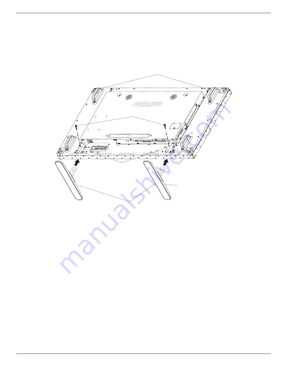
1.4.  Installing and Removing Table Stands (optional)

To install table stands:

1.  Ensure your display is powered off.
2.  Spread a protective sheet on a flat surface.
3.  Grab the carrying handles and place the display face-down on the protective sheet. 
4.  After inserting the stand in the guide block, tighten the screws on both sides of the display.
NOTE:    The longer side of the stand should face the front of the display.

Carrying handle

Thumbscrews

Longer portions face the front

Table stand

Guide block

To remove table stands:

1.  Power off the display.
2.  Spread a protective sheet on a flat surface.
3.  Grab the carrying handles and place the display face-down on the protective sheet. 
4.  Remove screws using a screwdriver and place them in a safe place for reuse.

Summary of Contents for Signage Solutions BDL5588XC

Page 1: ...www philips com welcome BDL5588XC V1 10 User Manual English ...

Page 2: ...avoid the risk of shock or permanent damage to the set do not expose the display to dust rain water or an excessively moist environment If your display becomes wet wipe it with dry cloth as soon as possible If a foreign substance or water gets in your display turn the power off immediately and disconnect the power cord Then remove the foreign substance or water and send the unit to the maintenance...

Page 3: ...nty EC Declaration of Conformity This device complies with the requirements set out in the Council Directive on the Approximation of the Laws of the Member States relating to Electromagnetic Compatibility 2014 30 EU Low voltage Directive 2014 35 EU and RoHS directive 2011 65 EU This product has been tested and found to comply with the harmonized standards for InformationTechnology Equipment these ...

Page 4: ...tandards PN 93 T 42107 and PN 89 E 06251 Electric Magnetic and Electromagnetic Fields EMF 1 We manufacture and sell many products targeted at consumers which like any electronic apparatus in general have the ability to emit and receive electromagnetic signals 2 One of our leading Business Principles is to take all necessary health and safety measures for our products to comply with all applicable ...

Page 5: ...NEUTRAL N BROWN LIVE L GREEN YELLOW EARTH E 1 The GREEN YELLOW wire must be connected to the terminal in the plug which is marked with the letter E or by the Earth symbol or coloured GREEN or GREEN YELLOW 2 The BLUE wire must be connected to the terminal which is marked with the letter N or coloured BLACK 3 The BROWN wire must be connected to the terminal which marked with the letter L or coloured...

Page 6: ... LCD panel CCFL LED 电路板组件 底座 电源线 其它线材 遥控器 电路板组件包括印刷电路板及其构成的零部件 如电阻 电容 集成电路 连接器等 本表格依据SJ T 11364的规定标志 O 表示该有害物质在该部件所有均质材料中的含量均在 GB T 26572规定的限量要求以下 X 表示该有害物质至少在该部件的某一均质材料中的含量超出 GB T26572规定的限量要求 但是符 合欧盟RoHS法规要求 属于豁免部分 备注 上表仅做为范例 实际标示时应依照各产品的实际部件及所含有害物质进行标示 10 環保使用期限 此標識指期限 十年 電子信息產品中含有的有害物質在正常使用的條件下不會發生外泄或突變 電子信息產品用戶使用該電子信息產品不會對環境造成嚴重污染或對其人身 財產造成嚴重損害的期限 ...

Page 7: ... 底座 電源線 其他線材 遙控器 備考1 係指該項限用物質之百分比含量未超出百分比含量基準值 備考2 係指該項限用物質為排除項目 警語 使用過度恐傷害視力 注意事項 1 使用30分鐘請休息10分鐘 2 未滿2歲幼兒不看螢幕 2歲以上每天看螢幕不要超過1小時 警告使用者 此為甲類資訊技術設備 於居住環境中使用時 可能會造成射頻擾動 在此種情況下 使用者會被要 求採取某些適當的對策 Turkey RoHS Türkiye Cumhuriyeti EEEYönetmeliğine Uygundur Ukraine RoHS Обладнання відповідає вимогам Технічного регламенту щодо обмеження використання деяких небезпечних речовин в електричному та електронному ...

Page 8: ...nts or consumables or parts or spares do not contain Lead Mercury Cadmium Hexavalent Chromium polybrominated biphenyls and polybrominated diphenyl ethers beyond a maximum concentration value of 0 1 by weight in homogenous materials for lead mercury hexavalent chromium polybrominated biphenyls and polybrominated diphenyl ethers and of 0 01 by weight in homogenous materials for cadmium except of exe...

Page 9: ...de de assistência técnica autorizada Information for EAC Month and year of manufacturing please refer information in Rating label Name and location of manufacturer ООО Профтехника Адрес 3 й Проезд Марьиной рощи 40 1 офис 1 Москва 127018 Россия Importer and information Наименование организации ООО Профтехника Адрес 3 й Проезд Марьиной рощи 40 1 офис 1 Москва 127018 Россия Контактное лицо Наталья Ас...

Page 10: ...4 3 3 2 Connecting an external audio device 15 3 4 Connecting Multiple Displays in a Daisy chain Configuration 16 3 4 1 Display control connection 16 3 4 2 Digital video connection 16 3 4 3 Analog video connection 17 3 4 4 IR daisy chain Connection 17 3 5 IR connection 17 3 6 IR Pass through Connection 18 3 7 Wire connecting to Network 18 4 Operation 19 4 1 Watch the ConnectedVideo Source 19 4 2 C...

Page 11: ...2 Edge Alignment Pin Thumb Screw IR Sensor Cable IR Cable Differences according to regions Display design and accessories may differ from those illustrated above NOTES For all other regions apply a power cord that conforms to the AC voltage of the power socket and has been approved by and complies with the safety regulations of the particular country You might like to save the package box and pack...

Page 12: ...and in the guide block tighten the screws on both sides of the display NOTE The longer side of the stand should face the front of the display Carrying handle Thumbscrews Longer portions face the front Table stand Guide block To remove table stands 1 Power off the display 2 Spread a protective sheet on a flat surface 3 Grab the carrying handles and place the display face down on the protective shee...

Page 13: ...the wall mounting kit use M6 mounting screws having a length 10 mm longer than the thickness of the mounting bracket and tighten them securely 5 Unit without base weight 26 5 kg The equipment and its associated mounting means still remain secure during the test For use only with UL Listed Wall Mount Bracket with minimum weight load 26 5 kg 1 5 1 VESA Grid BDL5588XC 400 H x 400 V mm Caution To prev...

Page 14: ...unting in Portrait Position This display can be installed in portrait position 1 Remove the table stand if attached 2 Rotate 90 degrees anticlockwise The logo should be bristling when facing the display at the back 90 90 ...

Page 15: ...rew for easy installing Using Edge Alignment Kit 1 on adjacent four displays 2 3 4 5 6 7 8 1 Using Edge Alignment Kit 2 on adjacent two displays Install the Edge Alignment Kit 2 with 2 PCS of M4 screw 1 2 3 4 NOTE When installing the edge alignment kit please consult a professional technician for proper installation We accept no liability for installations not performed by a professional technicia...

Page 16: ...nishiing Kit Top 1PC Edge Finishiing Kit Bottom 1PC Screw QTY is different depending on models Edge Finishiing Kit Right 1PC Corner 4PCS Installing Edge Finishing Kit for 2x2 Display Configuration Edge Finishiing Kit Top 2PCS Edge Finishiing Kit Left 2PCS Screw QTY is different depending on models Edge Finishiing Kit Bottom 2PCS Edge Finishiing Kit Right 2PCS Connector 4PCS Connector 4PCS For more...

Page 17: ...hlight bar up to adjust the selected item while OSD menu is on 7 button Move the highlight bar down to adjust the selected item while OSD menu is on 8 MENU button Return to previous menu while OSD menu is on or to activate the OSD menu when OSD menu is off 9 Remote control sensor and power status indicator Receives command signals from the remote control Indicates the operating status of the displ...

Page 18: ... 8 HDMI1 IN 9 HDMI2 IN HDMI video audio input 10 DVI IN DVI D video input 11 DVI OUT VGA OUT DVI orVGA video output 12 DisplayPort IN 13 DisplayPort OUT DisplayPort video input output 14 VGA IN D Sub VGA video input 15 COMPONENT IN BNC ComponentYPbPr video source input 16 Y CVBS Video source input 17 PC LINE IN Audio input forVGA source 3 5mm stereo phone 18 SPEAKER SWITCH Internal speaker on off ...

Page 19: ... Navigate through menus and choose items 7 button Confirm an entry or selection 8 ADJUST button Access currently available options picture and sound menus 9 MUTE button Press to turn the mute function on off 10 COLOR buttons Choose tasks or options 11 Number ID SET ENTER button Enter text for network setting Press to set the display ID Refer to 2 3 2 ID Remote Control for more detail 12 FORMAT but...

Page 20: ...control For example press 0 and 1 for display No 1 press 1 and 1 for display No 11 The numbers available are from 01 255 2 Not pressing any button within 10 seconds will exit the ID Mode 3 If an error pressing of buttons other than the digits occured wait 1 second after the red LED lights off and then lights up again then press the correct digits again 4 Press ENTER button to confirm The red LED b...

Page 21: ...attery acid as it can damage your skin NOTE If you do not intend to use the remote control for a long period remove the batteries 2 3 4 Handling the remote control Do not subject to strong shock Do not allow water or other liquid to splash the remote control If the remote control gets wet wipe it dry immediately Avoid exposure to heat and steam Other than to install the batteries do not open the r...

Page 22: ...al Equipment 3 1 Connecting External Equipment DVD VCR VCD 3 1 1 Using COMPONENT video input DVD VCR VCD AUDIO IN COMPONENT IN YPbPr COMPONENT Out YPbPr Audio Out 3 1 2 UsingVideo Source input DVD VCR VCD AUDIO IN Y CVBS IN Y CVBS Out ...

Page 23: ...3 1 3 Using HDMI video input DVD VCR VCD HDMI Out HDMI IN 3 2 Connecting a PC 3 2 1 UsingVGA input PC VGA IN VGA AUDIO IN VGA Out D Sub 15 pin Audio Out 3 2 2 Using DVI input PC VGA AUDIO IN DVI Out Audio Out DVI IN ...

Page 24: ...DL5588XC 14 3 2 3 Using HDMI input PC HDMI Out HDMI IN 3 2 4 Using DisplayPort input PC DisplayPort Out DisplayPort IN 3 3 Connecting Audio Equipment 3 3 1 Connecting external speakers External speakers ...

Page 25: ...BDL5588XC 15 3 3 2 Connecting an external audio device Stereo Amplifier AUDIO OUT Audio In ...

Page 26: ...SPLAY 1 to the RS232C IN connector of DISPLAY 2 DISPLAY 1 PC DISPLAY 2 RS 232C IN RS 232C RS 232C OUT RS 232C IN DISPLAY 1 PC DISPLAY 2 RJ 45 RS 232C OUT RS 232C IN RJ 45 3 4 2 Digital video connection Connect the DVI OUT VGA OUT connector of DISPLAY 1 to the DVI IN connector of DISPLAY 2 PC DVI IN DVI DVI VGA OUT DVI IN DISPLAY 1 DISPLAY 2 Connect the DP OUT connector of DISPLAY 1 to the DP IN co...

Page 27: ...VI OUT VGA OUT connector of DISPLAY 1 to the VGA IN connector of DISPLAY 2 PC DISPLAY 1 DISPLAY 2 VGA IN VGA DVI VGA OUT VGA IN 3 4 4 IR daisy chain Connection Connect IR Sensor Cable to DISPLAY 1 and connect the RS232C OUT connector of DISPLAY 1 to the RS232C IN connector of DISPLAY 2 DISPLAY 2 DISPLAY 1 RS 232C OUT IR Sensor Cable RS 232C IN IR IN 3 5 IR connection IR IN External IR Receiver ...

Page 28: ...ork Page 19 for more detail PC RJ 45 RJ 45 ROUTER INTERNET To setup the network 1 Switch on the router and switch on its DHCP setting 2 Connect the router to this display with an Ethernet cable 3 Press HOME button on the remote control then select Setup 4 Select Connect to network then press button 5 Follow the on screen instructions to install the network 6 Wait for this display to find the netwo...

Page 29: ...4 3 1 Set up the network 1 Connect your display and the computer to the same home network See illustration below to connect your display to a network 2 Switch on your computer and the router Single display setup PC RJ 45 RJ 45 ROUTER Multiple display setup PC RJ 45 RJ 45 RJ 45 ROUTER DISPLAY 1 DISPLAY 2 NOTE If the apparatus does not return to DLNA mode due to external electrical disturbances e g ...

Page 30: ...se the media file by right click On the submenu from PlayTo You can find all displays connected to your network Choose the display and click the media file to play Play files 1 Press SOURCE button 2 Choose Network and press button 3 Choose a file from the content browser and press button to start playing 4 Press the PLAY buttons on the remote control to control playing Tips Choose the top bar to f...

Page 31: ...rent speeds To stop the video press H button Movie options While playing video press OPTIONS button then press button to choose an option Subtitles Choose the available subtitle settings Subtitle language Choose the language for subtitles if available Shuffle Enable or disable random play of video files Repeat Choose Repeat to play the video file repeatedly or Play once to play the video file once...

Page 32: ... z abc ABC 123 www Backspace 3 Move the cursor to icon and press button History Bookmark Web Address X Internet www google com http www google com w w w w w w w w w w w w w w w w w w w w w w w w w w w w w w w w w w w w w w w w w w w w w w w w w w w w w w w w w w w w w w w w w w w w w w w w w w w w w w w w w w w w w w w w w w w w w w w w w w w w w w w w w w w w w w w w w w w w w w w w w w w w w w w...

Page 33: ...ust the brightness of this display s backlight Colour Adjust the colour saturation of the picture Sharpness Adjust the sharpness of the picture Noise reduction Choose the amount of noise reduction for the picture MPEG artifact reduction Smoothen transitions and haziness in the digital picture Picture enhancement Fine tune each pixel to match surrounding pixels and produce a brilliant high definiti...

Page 34: ...tings Turn on or off the internal speakers Clear sound Enhance sound quality Audio out format Choose the type of audio output through the digital audio output connector HDMI only Audio out delay Automatically sync the image on this display to the audio from a connected home theatre Audio out offset Adjust the setting for audio output delay Available if Audio out delay is switched on Sync Volume Ch...

Page 35: ...n multiple displays are connected RS232 Routing Select control port RS232 Select RS232 Control LAN RJ 45 Select LAN control IR Select the operation mode of the remote control when multiple displays are connected via an RS232C connection IR Control Normal All displays can be operated normally by the remote control unit Primary Designate this display as the primary display for remote control operati...

Page 36: ... Advanced Help Status Activate Enable H monitors V monitors Position Frame comp Frame comp H Frame comp V Switch on delay RS232 Routing Auto ID Tiling tool 1 Enter activate menu Picture Sound Tiling Network General settings Advanced Help Status Activate 2 Enter activate key in OSD Cancel Done Clear _ 3 Press button and it will pop out the on screen keyboard You can move the cursor to enter the act...

Page 37: ...educe the power consumption automatically NOTES Factory default setting is low power standby but user could not reset it to default after setting Eco mode to Normal by Factory reset in MENU However user can still change the ECO mode back to low power standby manually Auto search Choose to let this display detect and display available signal sources automatically Clock Set the current date and time...

Page 38: ...ting Off On Schedule 1 Schedule 2 Schedule 3 Schedule 4 Schedule 5 Schedule 6 Schedule 7 2 Go to Source and choose input source If Source USB is chosen You need to set playliist If Source BROWSER is chosen You need to set URL address NOTE If Source Autoplay is chosen You need to create a folder named philips in the root directory of the USB and put the files pictures or videos you want to display ...

Page 39: ...keyboard function except the and POWER button NOTE To disable the lock function from Local KB lock or RC lock item press buttons and 1 9 9 8 on the remote control Pixel shift For video input sources you may choose On to move the screen image automatically to protect the display from burn in or after image symptoms 30 seconds after not operating the display Smart power Choose a backlight level to o...

Page 40: ...option will start running the cooling fan if the temperature of 45 C 113 F is reached and stop running the cooling fan if the temperature of 43 C 109 F A temperature warning message will be shown on the screen if the temperature reaches 58 C 136 F All key functions except key will then be disabled Once the temperature reaches 60 C 140 F the display power will be shut down automatically Factory set...

Page 41: ... 30 MVC 1920x1080i field rate 50 60Hz 1920x1080p frame rate 24 25 30Hz 1280x720p frame rate 50 60Hz 30 ts m2ts mts AVCHD MPEG 2 1920x1080 25p 30p 50i 60i 30 MPEG 1 L1 L2 MPEG 1 2 2 5 L3 AAC HE AAC v1 v2 AC3 E AC3 Dolby Pulse MPEG 4 ASP 1920x1080 25p 30p 50i 60i 30 H 264 1920x1080 25p 30p 50p 60p 60i 30 ts m2ts mts AVCHD MVC 1920x1080i field rate 50 60Hz 1920x1080p frame rate 24 25 30Hz 1280x720p f...

Page 42: ... Pro wav PC LPCM 192 768 LPCM aif mac aiff mac LPCM 192 768 LPCM aac mp4 m4a AAC 48 1024 AAC HE AAC v1 v2 pls m3u Playlists m4a M4A 48 1024 AAC HE AAC v1 v2 NOTES Sound or video may not work if the contents have a standard bit rate frame rate above the compatible Frame sec listed in the table above Video content with a Bit rate or Frame rate larger than the rate specified in the table above can ca...

Page 43: ... HDTV Resolution Standard Resolution Active Resolution Refresh Rate Pixel Rate Aspect Ratio Stand for Mode H Pixels V Lines 720p 1280 720 50 Hz 74 25 MHz 16 9 Normally DVB Mode 60 Hz 1080i 1920 1080 25 Hz 74 25 MHz 16 9 Normally ATSC Mode 30 Hz 1080p 1920 1080 50 Hz 148 5 MHz 16 9 Normally ATSC Mode 60 Hz The PC text quality is optimum in HD 1080 mode 1920 x 1080 60Hz Your PC display screen might ...

Page 44: ...el or picture element is composed of three sub pixels in the primary colors of red green and blue Many pixels together form an image When all sub pixels of a pixel are lit the three colored sub pixels together appear as a single white pixel When all are dark the three colored sub pixels together appear as a single black pixel Other combinations of lit and dark sub pixels appear as single pixels of...

Page 45: ...ome liquid crystal display LCD panels This is known within the industry as Mura which is a Japanese term for unevenness It is used to describe an irregular pattern or area in which uneven screen uniformity appears under certain conditions Mura is a result of the deterioration of the liquid crystal alignment layer and is most commonly caused by long term operation under high ambient temperatures It...

Page 46: ...int free cloth If the surface becomes dirty soak a soft lint free cloth in a mild detergent solution Wring the cloth to remove excess liquid Wipe the surface of the display to remove dirt Then use a dry cloth of the same type to dry Do not scratch or hit the surface of the panel with fingers or hard objects of any kind Do not use volatile substances such as insert sprays solvents and thinners Cabi...

Page 47: ...e Make sure that both video inputs and sound inputs are correctly connected Can see picture but no sound is heard 1 Improperly connected source signal cable 2 Volume is turned all the way down 3 Mute is turned on 4 No external speaker connected 1 Make sure that both video inputs and sound inputs are correctly connected 2 Press or button to hear sound 3 Switch MUTE off by using the button 4 Connect...

Page 48: ... is the RC working Daisy chain no RS232 connected and IR cable No need setting just to connect with IR cables and control by IR This way has out of synchronizm phenomenon Suggest to use above setting with RS 232 cable ...

Page 49: ...ck x 1 8 pin 10 100 LAN Port HDMI Input HDMI Jack x 2 Type A 18 pin Digital RGB TMDS Video Audio MAX Video 720p 1080p 1920 x 1080 60 Hz WUXGA Audio 48 KHz 2 Channel L R Supports LPCM only DVI D Input DVI D jack Digital RGB TMDS Video VGA Input D Sub Jack x 1 15 pin Analog RGB 0 7V p p 75Ω H CS V TTL 2 2kΩ SOG 1V p p 75Ω MAX 720p 1080p 1920 x 1080 60 Hz WUXGA DVI I DVI D VGA Output DVI I Jack x 1 2...

Page 50: ... Energy Efficiency Class B Visible Screen Size 138 7 cm 54 6 inch On Mode Power Consumption W 155 W Annual Energy Consumption kWh 226 kWh Standby Power Consumption W 0 50 W Off Mode Power Consumption W 0 50 W Display Resolution Pixels 1920 x 1080 Network Standby W 0 8W Environmental Condition Item Specifications Temperature Operational 0 40 C Storage 20 60 C Humidity Operational 20 80 RH No conden...

Page 51: ...s N V All rights reserved Philips and the Philips Shield Emblem are registered trademarks of Koninklijke Philips N V and are used under license from Koninklijke Philips N V Specifications are subject to change without notice ...

Reviews: