Version 1.0
MCM390
©
3141 785 30170
Micro System
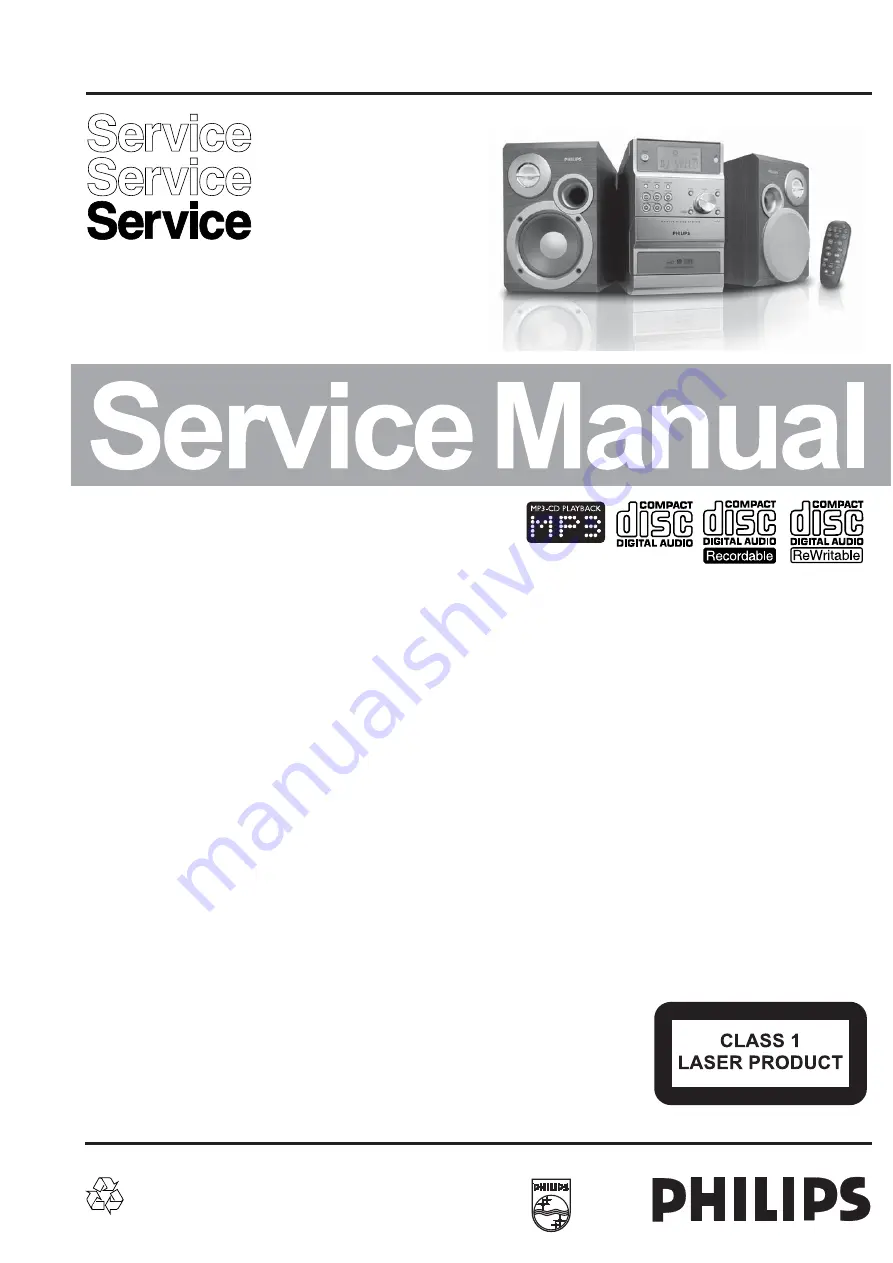
all versions
Published by YT 0519 Service Audio Printed in The Netherlands Subject to modification
©
Copyright 2005 Philips Consumer Electronics B.V. Eindhoven, The Netherlands
All rights reserved. No part of this publication may be reproduced, stored in a retrieval
system or transmitted, in any form or by any means, electronic, mechanical, photocopying,
or otherwise without the prior permission of Philips.
Handling chip components ............................................................ 1-1
Leadfree and safety information ................................................... 1-2
Technical specification .................................................................. 2-1
Service tools .................................................................................. 2-1
Service measurement setup ......................................................... 2-2
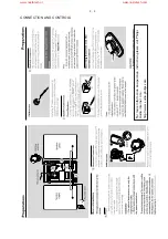
Connections and controls ..................................................... 3-1...3-2
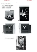
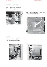
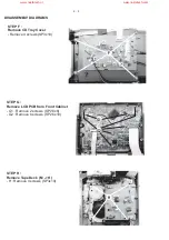
Disassembly diagram ............................................................ 4-1...4-3
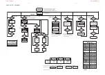
Service test program ..................................................................... 5-1
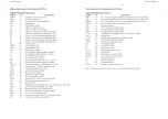
Pin description of ICs ............................................................ 5-2...5-3
Set block diagram ......................................................................... 6-1
Set wiring diagram ........................................................................ 6-2
Display and MCU board
circuit
diagram
.......................................................................... 7-1
layout
diagram
.......................................................................... 7-2
Tuner board (ECO6 cenelec)
circuit
diagram
.......................................................................... 8-1
layout
diagram
.......................................................................... 8-2
tuner adjustment table .............................................................. 8-2
Tuner board (ECO6 noncenelec)
circuit
diagram
.......................................................................... 8-3
layout
diagram
.......................................................................... 8-4
tuner adjustment table .............................................................. 8-4
Cassette board
circuit
diagram
.......................................................................... 9-1
layout
diagram
.......................................................................... 9-2
tape deck adjustment ............................................................... 9-3
tape deck wiring diagram ......................................................... 9-3
CD board
circuit
diagram.
............................................................. 10-1...10-2
layout
diagram
........................................................................ 10-3
MP3-CD2002 BOARD
circuit diagram ........................................................................ 10-4
layout
diagram
........................................................................ 10-5
Main and power board
circuit diagram. ........................................................................11-1
layout
diagram
...............................................................11-2...11-4
Exploded view (main set) ............................................................ 12-1
Mechanical partslist ..................................................................... 12-2
Electrical partslist ..............................................................
13-1... 13-2
TABLE OF CONTENTS
www.nostatech.nl
www.nostatech.com
Summary of Contents for MCM390
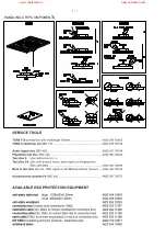
Page 2: ...1 1 HANDLING CHIP COMPONENTS www nostatech nl www nostatech com ...
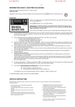
Page 3: ...1 2 www nostatech nl www nostatech com ...
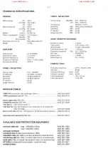
Page 4: ...2 1 www nostatech nl www nostatech com ...
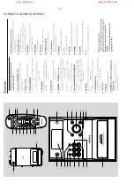
Page 6: ...3 1 CONNECTION AND CONTROLS www nostatech nl www nostatech com ...
Page 12: ...5 2 5 2 www nostatech nl www nostatech com ...
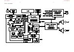
Page 14: ...6 1 6 1 SET BLOCK DIAGRAM www nostatech nl www nostatech com ...
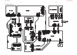
Page 15: ...6 2 6 2 SET WIRING DIAGRAM www nostatech nl www nostatech com ...
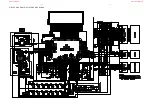
Page 16: ...7 1 7 1 CIRCUIT DIAGRAM DISPLAY AND MCU BOARD www nostatech nl www nostatech com ...
Page 22: ...9 1 9 1 CIRCUIT DIAGRAM CASSETTE BOARD www nostatech nl www nostatech com ...
Page 25: ...10 1 10 1 CIRCUIT DIAGRAM CD BOARD PART 1 www nostatech nl www nostatech com ...
Page 26: ...10 2 10 2 CIRCUIT DIAGRAM CD BOARD PART 2 www nostatech nl www nostatech com ...
Page 30: ...11 1 11 1 CIRCUIT DIAGRAM MAIN and POWER BOARD www nostatech nl www nostatech com ...
Page 31: ...11 2 11 2 LAYOUT DIAGRAM MAIN BOARD COMPONENT SIDE www nostatech nl www nostatech com ...
Page 32: ...11 3 11 3 LAYOUT DIAGRAM MAIN BOARD COPPER SIDE www nostatech nl www nostatech com ...
Page 33: ...11 4 11 4 LAYOUT DIAGRAM POWER BOARD www nostatech nl www nostatech com ...
Page 34: ...12 1 12 1 EXPLODED VIEW DIAGRAM 66 65 67 70 71 72 www nostatech nl www nostatech com ...


