Version 1.2
MCD196
©
3141 785 31612
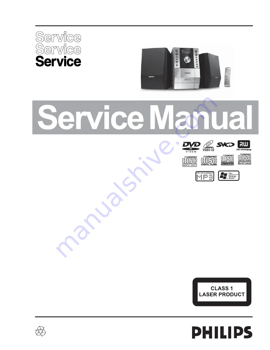
DVD Micro theatre
all versions
Published by LX 0720 Service Audio Subject to modification
©
Copyright 2007 Philips Consumer Electronics B.V. Eindhoven, The Netherlands
All rights reserved. No part of this publication may be reproduced, stored in a retrieval
system or transmitted, in any form or by any means, electronic, mechanical, photocopying,
or otherwise without the prior permission of Philips.
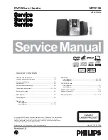
Handling chip components ...........................................................1-1
Leadfree and safety information ....................................................1-2
Technical specification ...................................................................2-1
Service tools .................................................................................2-1
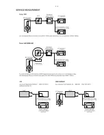
Service measurement setup ..........................................................2-2
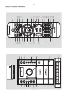
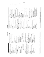
Connections and controls ......................................................3-1...3-4
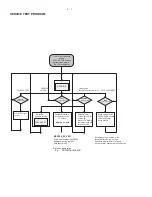
Service test program .....................................................................4-1
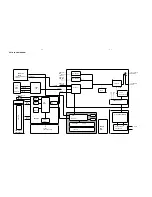
Block diagram ................................................................................5-1
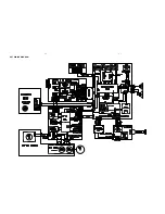
Wiring diagram .............................................................................6-1
Display Board
circuit
diagram
..........................................................................7-1
layout diagram ..................................................................7-2...7-3
Main Board
circuit diagram ..................................................................8-1...8-2
layout diagram .................................................................8-3...8-4
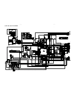
DVD MPEG Board
circuit
diagram.
.........................................................................9-1
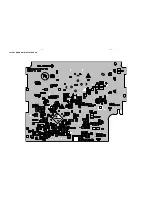
layout
diagram
..........................................................................9-2
Exploded view diagram ...............................................................10-1
Mechanical partslist .....................................................................10-2
Electrical partslist............................................................... 11-1...11-
3
TABLE OF CONTENTS
Summary of Contents for MCD196
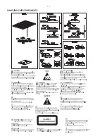
Page 2: ...1 1 ...
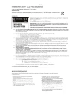
Page 3: ...1 2 ...
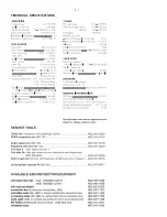
Page 4: ...2 1 TECHNICAL SPECIFICATIONS ...
Page 5: ...2 2 ...
Page 6: ...3 1 CONNECTION AND CONTROLS ...
Page 7: ...3 2 CONNECTION AND CONTROLS ...
Page 10: ...6 1 6 1 SET WIRING DIAGRAM ...
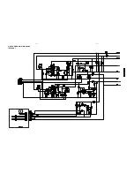
Page 11: ...7 1 7 1 CIRCUIT DIAGRAM DISPLAYBOARD ...
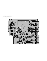
Page 12: ...7 2 7 2 LAYOUT DIAGRAM DISPLAY BOARD ...
Page 13: ...LAYOUT DIAGRAM DISPLAY BOARD 7 3 7 3 ...
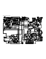
Page 14: ...CIRCUIT DIAGARM MAIN BOARD 8 1 8 1 ...
Page 15: ...8 2 8 2 CIRCUIT DIAGRAM MAIN BOARD TAPE PART ...
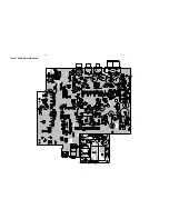
Page 16: ...LAYOUT DIAGRAM MAIN BOARD 8 3 8 3 ...
Page 17: ...LAYOUT DIAGRAM MAIN BOARD 8 4 8 4 ...
Page 18: ...9 1 9 1 CIRCUIT DIAGRAM DVD MPEG BOARD MPEG is not repaired diagram for referrence only ...
Page 19: ...LAYOUT DIAGRAM DVD MPEG BOARD MPEG is not repaired diagram for referrence only 9 2 9 2 ...

