background image

Version 1.

2

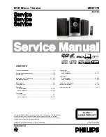
MCD170

 3141 785 3330

2

DVD Micro Theater

-/98/12/58

Published by LX 0923 Service Audio    Subject to modification

©

Copyright 2009 Philips Consumer Electronics B.V. Eindhoven, The Netherlands

All rights reserved. No part of this publication may be reproduced, stored in a retrieval
system or transmitted, in any form or by any means, electronic, mechanical, photocopying,
or otherwise without the prior permission of Philips.

CONTENTS

Technical specification ..................................................................1-2            

Service measurement setup..........................................................1-3             
Service aids  .................................................................................1-4          

Instructions on CD playability ................................................2-1..2-2
Disassembly diagram............ .....................................,,,,,,,,...........3-1

Block diagram................................................................................4-1
Wiring diagram ..............................................................................4-2

Main board
     Circuit diagram ..................................................................5-1..5-2
     Layout diagram..................................................................5-3..5-4

Front board
     Circuit diagram .........................................................................6-1
     Layout diagram..................................................................6-2..6-3

Tape board
     Circuit diagram .........................................................................7-1
     Layout diagram..................................................................7-2..7-3

DVD board
     Circuit diagram ..................................................................8-1..8-5
     Layout diagram.........................................................................8-6

Exploded view diagram .................................................................9-1
Mechanical parts list ...............................................................9-2

..9-3

Electrical parts list........................................................................10-1

Summary of Contents for MCD170

Page 1: ...l photocopying or otherwise without the prior permission of Philips CONTENTS Technical specification 1 2 Service measurement setup 1 3 Service aids 1 4 Instructions on CD playability 2 1 2 2 Disassembly diagram 3 1 Block diagram 4 1 Wiring diagram 4 2 Main board Circuit diagram 5 1 5 2 Layout diagram 5 3 5 4 Front board Circuit diagram 6 1 Layout diagram 6 2 6 3 Tape board Circuit diagram 7 1 Layo...

Page 2: ...oding MPEG 2 MPEG 1 Video DAC 10 Bits Signal System PAL NTSC Video Format 4 3 16 9 Video S N 56 dB minimum Composite Video Output 1 0 Vp p 75 ohm S Video output Y 1 0 Vp p 75 ohm C 0 286 Vp p 75 ohm Audio DAC 24Bits 96 kHz Total Harmonic Distortion 1 Frequency Response 4 Hz 20 kHz 44 1kHz 4 Hz 22 kHz 48 kHz 4 Hz 44 kHz 96 kHz Digital Output SPDIF Sony Philips digital interface coaxial Total harmon...

Page 3: ...15kHz e g 7122 707 48001 LF Voltmeter e g PM2534 DUT S N and distortion meter e g Sound Technology ST1700B Frame aerial e g 7122 707 89001 Tuner AM MW LW To avoid atmospheric interference all AM measurements have to be carried out in a Faraday s cage Use a bandpass filter or at least a high pass filter with 250Hz to eliminate hum 50Hz 100Hz RF Generator e g PM5326 Ri 50 Bandpass 250Hz 15kHz e g 71...

Page 4: ...ng make sure that you are connected with the same potential as the mass of the set via a wrist wrap with resistance Keep components and tools also at this potential ESD CLASS 1 LASER PRODUCT GB Safety regulations require that the set be restored to its original condition and that parts which are identical with those specified be used Safety components are marked by the symbol Lead free ...

Page 5: ...T OK check playability N Y playability ok check playability check playability return set Customer complaint CD related problem fast lens cleaning 1 2 3 For flap loaders access to CD drive possible cleaning method 4 is recommended INSTRUCTIONS ON CD PLAYABILITY 2 1 Exchange CDM 1 4 For description see following pages ...

Page 6: ...viously caused by a scratched dirty or copy protected CD In case problems remain the customer is requested to contact the workshop directly The lens cleaning method 3 should be mentioned in the addendum sheet The final wording in national language as well as the printing is under responsibility of the Regional Service Organizations 4 LIQUID LENS CLEANING Because the material of the lens is synthet...

Page 7: ...DISASSEMBLY DIAGRAM VIEW 3 1 3 1 ...

Page 8: ...SET BLOCK DIAGRAM 4 1 4 1 ...

Page 9: ...SET WIRING DIAGRAM 4 2 4 2 ...

Page 10: ...5 1 5 1 CIRCUIT DIAGRAM MAIN BOARD AMP PART ...

Page 11: ...5 2 5 2 CIRCUIT DIAGARM MAIN BOARD TUNER PART ...

Page 12: ...LAYOUT DIAGARM MAIN BOARD COMPONENT SIDE VIEW 5 3 5 3 ...

Page 13: ...LAYOUT DIAGARM MAIN BOARD COPPER SIDE VIEW 5 4 5 4 ...

Page 14: ...CIRCUIT DIAGRAM FRONT BOARD 6 1 6 1 ...

Page 15: ...LAYOUT DIAGARM FRONT BOARD COMPONENT SIDE VIEW 6 2 6 2 ...

Page 16: ...LAYOUT DIAGARM FRONT BOARD COPPER SIDE VIEW 6 3 6 3 ...

Page 17: ...CIRCUIT DIAGRAM TAPE BOARD TAPE is not repaired diagram for referrence only 7 1 7 1 ...

Page 18: ...LAYOUT DIAGARM TAPE BOARD COMPONENT SIDE VIEW 7 2 7 2 ...

Page 19: ...LAYOUT DIAGARM TAPE BOARD COPPER SIDE VIEW 7 3 7 3 ...

Page 20: ...3904 0 1uF BC25 CN8 1 2 3 4 5 6 Q8 8050 TP5 A Q3 2SK3018 2 3 1 R20 2 2K 680pF C7 R12 100K R34 5 1 EC10 47uF 16V 0 1uF BC26 TP6 B U2 SPHE8202T 128 102 101 100 99 98 97 96 95 94 93 92 91 90 89 88 87 86 85 84 83 82 81 80 79 103 104 105 106 107 108 109 110 111 112 113 114 115 116 117 118 119 120 121 122 123 124 125 126 127 64 61 62 59 60 58 57 56 53 54 55 51 50 49 48 47 46 45 44 43 42 40 41 65 78 77 7...

Page 21: ...VCC3 0 1uF BC31 R51 10K R47 NC U5 SDRAM1Mx16x4 23 24 25 26 29 30 31 32 33 34 17 18 15 16 19 37 38 39 2 4 5 7 8 10 11 13 42 44 45 47 48 50 51 53 36 20 1 27 28 41 22 40 3 9 43 49 6 12 46 52 35 21 54 14 A0 A1 A2 A3 A4 A5 A6 A7 A8 A9 CAS RAS LDQM WE CS CKE CLK UDQM D0 D1 D2 D3 D4 D5 D6 D7 D8 D9 D10 D11 D12 D13 D14 D15 NC BA0 VDD VDD VSS VSS A10 AP NC RFU VDDq VDDq VDDq VDDq VSSq VSSq VSSq VSSq A11 BA1...

Page 22: ... U_O 2 TV_DAC0 3 TV_DAC1 3 TV_DAC2 3 TV_DAC3 3 V_FSADJ 3 V_COMP 3 GND VVCC3 GND GND GND GND P 5V GND P 5V GND P 5V GND P 5V GND D7 BAV99 10pF C17 R54 75 100pF C20 L15 1uH D5 BAV99 100pF C19 10pF C15 R53 75 100pF C22 D8 BAV99 L13 1uH 100pF C26 100pF C21 EC18 10uF 16V D6 BAV99 100pF C25 R52 75 10pF C16 10pF C18 R56 1K L14 1uH 100pF C24 L16 1uH 100pF C23 R55 75 CIRCUIT DIAGRAM DVD BOARD MPEG is not r...

Page 23: ...F C38 EC19 220uF 16V R79 10 47pF NC EC20 100uF 16V R63 100 Q10 2N3906 2 1 3 U8B NJM4558 5 6 7 8 4 120pF C41 120pF C33 Q15 2N3904 R73 470 R61 4 7K R67 10K C34 1uF R59 180 R85 4 7K R74 10K R89 470 C35 10uF 16V R70 9 1K C29 10uF 16V R76 18K R89 470 U9A NJM4558 3 2 1 8 4 R95 2 2K 200pF C30 R65 10K Q14 2N3904 R86 18K R66 24K 47pF C32 BC37 0 1uF 1200pF C40 1200pF C42 C28 10uF 16V NC C32 R64 NC R72 100 R...

Page 24: ...GND AGND AGND VCC3 GND GND GND P 5V P 5V GND GND P 12V GND GND EC1 220uF 16V L1 22uH 1 5A SMD EC6 220uF 16V L5 FB BC4 0 1uF EC5 100uF 16V C1 0 01uF D1 1N4001 0 1uF BC1 CN5 KEY 1 2 3 4 5 6 7 L8 FB CN3 UART 1 2 3 4 D2 SS14 SMD EC2 220uF 16V R10 2 2 R8 4 7K AV1 comp S video 1 2 3 4 5 6 7 8 9 10 1 2 3 4 5 6 7 8 9 10 CN4 AUDIO 1 2 3 4 R1 2 2 0 1uF BC6 TP2 R3 20K 0 1uF BC3 0 1uF BC9 R9 10K CB1 0 01uF R4...

Page 25: ...LAYOUT DIAGRAM DVD BOARD MPEG is not repaired diagram for referrence only 8 6 8 6 ...

Page 26: ...EXPLODED VIEW DIAGRAM 9 1 9 1 ...

Page 27: ...8 NEXT KEY 220 996510020825 VOL ROTRAY COVER 220 996510020825 VOL ROTRAY COVER 221 994000001295 DAMPER GEAR ASS Y 222 996510020812 STAND BY KEY 223 996510020842 SOURCE KEY 224 996510020791 ROTARY DECORATE RING 225 996510020214 CASS KEY WITH HOLDER J001 996500042448 CLOSE END WIRE CONNECTOR J002 994000001478 AC PLUG ADAPTOR 98 J003 996510020821 24P FFC 0 5mm L 190mm J004 996510020838 14P FFC 1mm L ...

Page 28: ...211 996510026077 CASSETTE DOOR 212 996510020836 DUST COVER 214 996510026048 PRESET KEY 215 996510026052 PRESET KEY 216 996510026055 PLAY KEY 217 996510026056 STOP KEY 218 996510026061 REVIEW KEY 219 996510026049 NEXT KEY 220 996510020825 VOL ROTRAY COVER 221 994000001295 DAMPER GEAR ASS Y 222 996510026069 STANDBY KAY 223 996510026064 SOURCE KEY 224 996510020791 ROTARY DECORATE RING 225 99651002607...

Page 29: ...2FNG U2 996510018852 IC UTC7808 U6 996510003984 IC CYT78L05 TO 92 FRONT BOARD ASSEMBLY D401 996500042438 LED LAMP 2x5x7mm WHITE J025 994000001244 V PHONE JACK 3 5MM J802 996510001316 USB SOCKET 4P P001 996510000998 ROTARY ENCODER P401 994000004367 OPTIC SENSER FM 6038TM2 5AN Q101 996510008369 TRANSISTORS MMBT8050D SOT23 Q101 996510008369 TRANSISTORS MMBT8050D SOT23 Q402 996510009308 TRANSISTORS MM...

Reviews: