Mechanical Instructions
4.
4.3.3
LTI/CTI Interface Panel
Remove the LTI/CTI Interface panel from the Mono Carrier, by
disconnecting it from connector 1212.
4.3.4
Top Control Assy/Panel
1.
Remove the two fixation screws.
2.
Push the assy a little bit upwards, and then pull it
backwards to release it from the front hinge.
3.
Lift the panel from its bracket, while releasing the two
fixation clamps. The panel hinges on the other side.
4.3.5
Linearity Assy/Panel
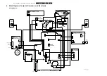
Figure 4-4 Linearity assy/panel removal
1.
Release the two fixation clamps [1] to lift the panel out of
the bracket [2].
4.4
Set Re-assembly
To re-assemble the whole set, do all processes in reverse
order.
Note: before you mount the rear cover, perform the following
checks:
•
Check whether the AC power cord is mounted correctly in
its guiding brackets.
•
Check whether all cables are replaced in their original
position
E_14480_051.eps
270204
1
1
2
Summary of Contents for L04LAA
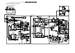
Page 36: ...Service Modes Error Codes and Fault Finding EN 36 L04L AA 5 E_06532_012 eps 130204 ...
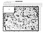
Page 58: ...58 L04L AA 7 Circuit Diagrams and PWB Layouts Layout Mono Carrier Part 1 Bottom Side Part 1 ...
Page 93: ...Spare Parts List EN 93 L04L AA 10 10 Spare Parts List Not applicable ...
Page 94: ...Revision List EN 94 L04L AA 11 11 Revision List First release ...


