


3-4
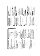
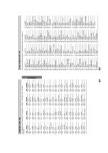
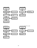
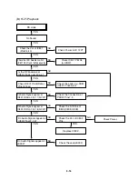
ELECTRICAL TROUBLESHOOTING GUIDE
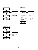
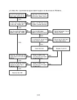
1. Power(SMPS) CIRCUIT
NO 5.3VA.
Replace the F101.
(Use the same Fuse)
Is the F101 normal?
Is the R101
normal?
Is the BD101
normal?
NO
NO
NO
NO
NO
NO
Replace the
BD101.
Replace the R101.
Is the D102
normal?
Check or Replace
the D102.
Replace the D112.
Replace the IC103.
YES
YES
YES
YES
YES
YES
YES
Is Vcc(8.5~21V) sup-
plied to IC101 Pin7?
NO
Is the D112 normal?
Is there about 2.5V
at the IC103 Vref?
Check the Main PCB
5.3VA/5.0V Line short?
(1) No 5.3VA (SYS/Hi-Fi/TUNER)
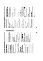
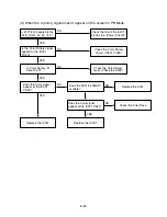
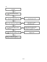
NO 12VA.
Check or Replace
the D110.
Is the Vcc(13V) supplied to
(+) terminal in D115, D117?
Check or Replace
the Motor Vcc.
Is the Vcc(12V) supplied to
(-) terminal in D115, D117?
NO
NO
Replace the D115.
YES
YES
YES
(2) No 12VA (TO CAP, DRUM MOTOR)
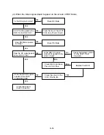
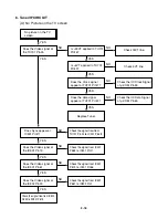
NO 5.0VA.
5.3VA Line Check.
Is 5.3VA put into
the Q160 Emitter?
Is about 5V put into
the Q160 Base?
Is the Q162 Base
“H”?
NO
NO
Check the Power
Control.
NO
Check or Replace the Q162,
R157, R158, R159, D121.
YES
YES
YES
Check or Replace
the Q162/Q160.
YES
(3) No 5.0V (SYS/Hi-Fi/TUNER)
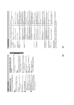
Summary of Contents for DVD755VR
Page 8: ...Directions for Use ...
Page 9: ......
Page 10: ......
Page 11: ......
Page 12: ......
Page 13: ......
Page 14: ......
Page 15: ......
Page 16: ......
Page 17: ......
Page 18: ......
Page 19: ......
Page 20: ......
Page 21: ......
Page 22: ......
Page 23: ......
Page 24: ......
Page 25: ......
Page 26: ...Personal Notes ...
Page 49: ......
Page 56: ...3 32 3 33 2 TU IF NICAM A2 CIRCUIT DIAGRAM EE MODE VIDEO TU MODE AUDIO COMBI SCART ...
Page 59: ...3 38 3 39 5 SCART JACK CIRCUIT DIAGRAM OPTIONAL PART COMBI SCART ...
Page 61: ...3 42 3 43 7 TIMER CIRCUIT DIAGRAM ...
Page 65: ...3 50 3 51 PRINTED CIRCUIT DIAGRAMS 1 MAIN P C BOARD LOCATION GUIDE ...
Page 66: ...3 52 3 53 2 SMPS P C BOARD LOCATION GUIDE 3 TIMER P C BOARD LOCATION GUIDE 4 KEY P C BOARD ...
Page 67: ......
Page 93: ......
Page 96: ...3 83 3 84 3 AUDIO CIRCUIT DIAGRAM COMBI SCART MTK 03 3 25 SR17447A ...
Page 97: ...3 85 3 86 4 AV JACK CIRCUIT DIAGRAM COMBI SCART MTK 03 3 25 SR17446A ...
Page 100: ...3 91 3 92 PRINTED CIRCUIT DIAGRAMS 1 MAIN P C BOARD LOCATION GUIDE ...
Page 101: ......
Page 133: ...MEMO ...
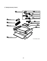
Page 134: ...EXPLODED VIEW 1 Deck Mechanism Exploded View 5 1 CONTENTS SECTION 5 MECHANISM OF DVD PART ...