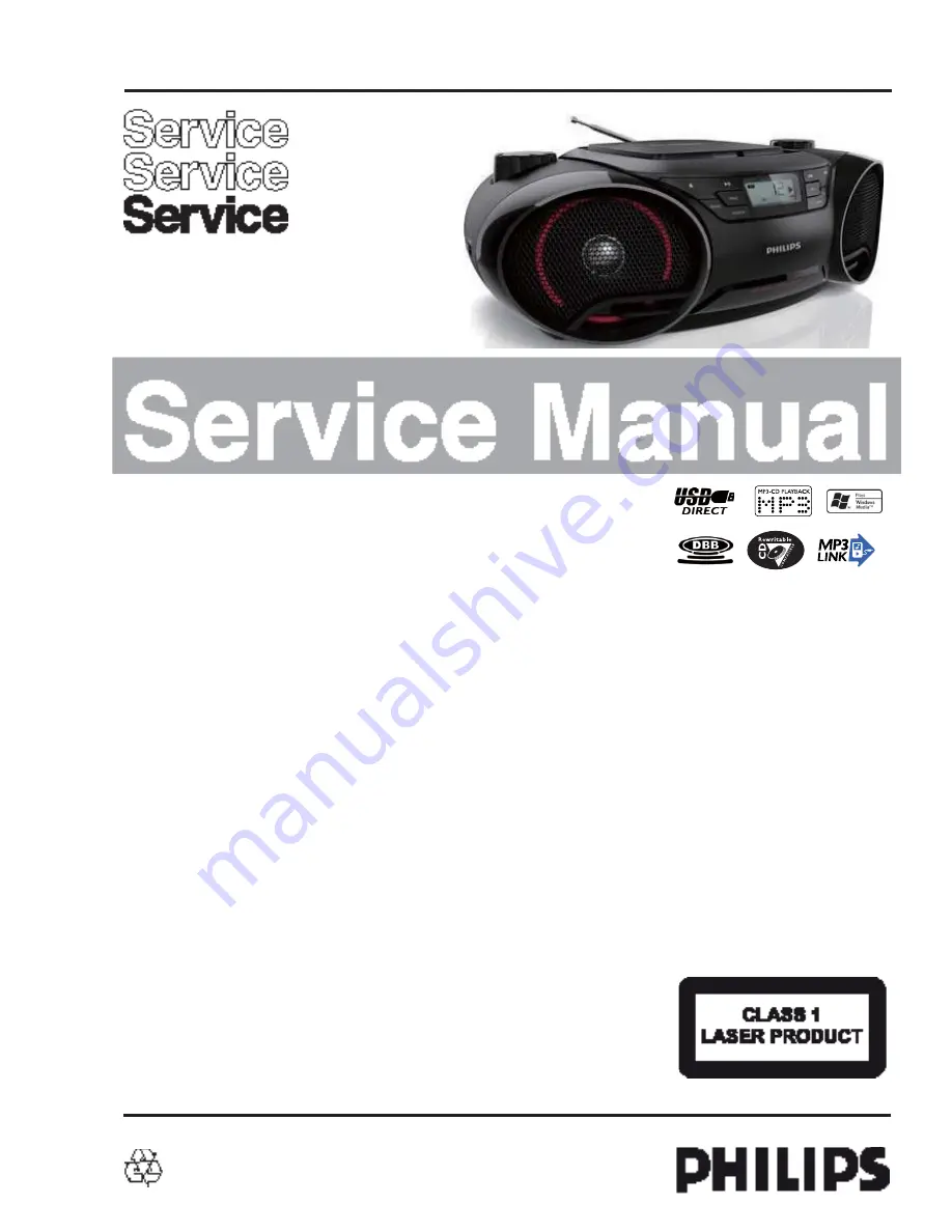
background image

Version 1.1

AZ3811

 3141 785 36371

MP3/WMA-CD 5W CD Soundmachine

/55/78/61

Published by SW 1121 Service Audio    Subject to modification

©

Copyright 2011 Philips Consumer Electronics B.V. Eindhoven, The Netherlands

All rights reserved. No part of this publication may be reproduced, stored in a retrieval
system or transmitted, in any form or by any means, electronic, mechanical, photocopying,
or otherwise without the prior permission of Philips.

CONTENTS

Technical specification and disassemble diagram ...........................1

Service and safety instructions.........................................................2

Block diagram ................................................................................3-1
Wiring diagram ..............................................................................4-1 

Main+Radio+Rectifier board
     Circuit diagram ..................................................................5-1..5-3 


     Layout diagram ..................................................................5-4..5-5

Display board
     Circuit diagram .........................................................................6-1
     Layout diagram .........................................................................6-2


Exploded view diagram .................................................................7-1
Revision list ...................................................................................8-1

Summary of Contents for AZ3811

Page 1: ...oduced stored in a retrieval system or transmitted in any form or by any means electronic mechanical photocopying or otherwise without the prior permission of Philips CONTENTS Technical specification and disassemble diagram 1 Service and safety instructions 2 Block diagram 3 1 Wiring diagram 4 1 Main Radio Rectifier board Circuit diagram 5 1 5 3 Layout diagram 5 4 5 5 Display board Circuit diagram...

Page 2: ...ion 8 x 1 5V D CELL UM1 R20 or equivalent Dimensions without Boxes W x H x D Weight including packing xxxKg CABINET Dimensions with Boxes W x H x D Material Finishing Spray Unit in Master carton N A Weight excluding packing and batteries xxxKg Weight excluding packing and batteries xxxKg Units in Dealer carton 1 set Remark FRONT PANEL SPECICFICATION Class No AZ3811 Issued Date 1 11 2011 1 11 2011 ...

Page 3: ...99 146V 196 264Vac V i 97 98 12 96 Refer to the section of Version Overview SAFETY requirements 55 77 78 73 Version 97 98 12 96 Voltage Selection Yes No No Frequency 60 50Hz 50 Hz 60 Hz ECO Power mode N A 1 8 Prated NOM A INPUT Class No GENERAL PART 1 GENERAL SPECICFICATION 1 11 2011 AZ3811 Issued Date A4 1 11 2011 2011 01 11 CMT NAME Mo Lam Kei KT CHECK 8 SH 190 4 Remarks 14W DC operation Backup ...

Page 4: ...AM80 Modulation Limit 6db Line Out Left Right CD 6 dB track Audio Disc 1 Trk 35 6 dB track Copy from Audio Disc 1 Trk 35 15 mW 2 dB at R Load 32 ohm max volume 0dB 1kHz CD Microphone 3 2 5W 1 Channels Lim 1dB At Cold Condition with 10 THD OUTPUT POWER 1 At THD 10 1KHz sinewave Main Operation At 500mW Output in flat Mode LOUDSPEAKER BOXES DC Operation 2 5W 1 Channels Lim 1dB Frequency Response 125H...

Page 5: ...ency Response 3dB volume max 20dB and DBB off mode 100Hz 10kHz Signal to Noise Ratio A weighted 62dBA Lim 57 dBA Channel Separation 10K 30dB Lim 16dB CD Shock sens 5kg THD 100 10kHz 2 Lim 3 0 Channel Separation 1K 40dB Lim 26dB DBB 8 2 dB at AUX 500mV 1kHz DBB effect USB PART Refer to Philips USB direct user requirement spec CLOCK CD SPECICFICATION Issued Date 1 11 2011 Class No AZ3811 2011 01 11 ...

Page 6: ...erit 30 25 dB 3 dB Limiting Point 17 25 dBf Stereo 46 dB Quieting 48 51 dBf Distortion RF 50mV m 80 3 5 Distortion RF 1mV Frq Dev 75 kHz 3 Modulation Hum 45 Search tuning sensitivity dBuV m 48 72 Search tuning sensitivity 24 32 19 35 dBf 1 0 Step 91 120dBf R F 31 91dBf RF 1V m RF a26 to 1V m 1 0 Wave Range Noise Limited Sensitivity 26 dB Image Rejection IF Rejection Lim 22 50 dBf 24 55 dBf 18 120 ...

Page 7: ...the top cabinet disassemble two 3 x 8 PB screws on bottom cabinet and unplug the 2pin cable between Main BD and power BD 2a 2b 2c 2 Disassemble front cabinet 2a 2b 2c disassemble the four 3 x 8 PB screws which connect top cabinet and front cabinet unplug 4pin speaker cable and 10pin FFC cable sperate top cabinet and PB screws which connect top cabinet and front cabinet unplug 4pin speaker cable an...

Page 8: ...3B Disassemble radio BD and CD deck 3 d 3 e 3 f 3B Disassemble radio BD and CD deck di bl th f 2 6 8 PWA disassemble the two 2 6 x 8 PB screws on radio BD unplug FM ANT unplug tunning knob and get out disassemble the four 2 6 x 8 PWA screws on CD deck and get out CD deck disassemble the two 2 6 x 8 PB screws on radio BD unplug FM ANT cable unplug tunning knob and get out the radio BD screws on CD ...

Page 9: ...3 g 3C Disassemble CD door take out CD door spring first pull out CD door when goring the CD door buckle with a screwdriver ...

Page 10: ...15kHz e g 7122 707 48001 LF Voltmeter e g PM2534 DUT S N and distortion meter e g Sound Technology ST1700B Frame aerial e g 7122 707 89001 Tuner AM MW LW To avoid atmospheric interference all AM measurements have to be carried out in a Faraday s cage Use a bandpass filter or at least a high pass filter with 250Hz to eliminate hum 50Hz 100Hz RF Generator e g PM5326 Ri 50 Bandpass 250Hz 15kHz e g 71...

Page 11: ...T OK check playability N Y playability ok check playability check playability return set Customer complaint CD related problem fast lens cleaning 1 2 3 For flap loaders access to CD drive possible cleaning method 4 is recommended INSTRUCTIONS ON CD PLAYABILITY 2 2 Exchange CDM 1 4 For description see following pages ...

Page 12: ...viously caused by a scratched dirty or copy protected CD In case problems remain the customer is requested to contact the workshop directly The lens cleaning method 3 should be mentioned in the addendum sheet The final wording in national language as well as the printing is under responsibility of the Regional Service Organizations 4 LIQUID LENS CLEANING Because the material of the lens is synthet...

Page 13: ...llegato allo stesso potenziale che quello della massa dell apparecchio tramite un braccialetto a resistenza Assicurarsi che i componenti e anche gli utensili con quali si lavora siano anche a questo potenziale Pour votre sécurité ces documents doivent être utilisés par des spécia listes agréés seuls habilités à réparer votre appareil en panne GB Safety regulations require that the set be restored ...

Page 14: ...perates properly after replacement if it was subject to electrostatic discharge during replacement its life might be shortened When replacing use a conductive mat soldering iron with ground wire etc to protect the laser diode form damage by static electricity And also the LSI and IC are same as above Soldering iron with ground wire or ceramic type Ground conductive wrist strap for body Conductive ...

Page 15: ...sts the fault must be located and corrected Repeat the above test with the DVD VIDEO PLAYER power plug reversed NEVER RETURN A DVD VIDEO PLAYER TO THE CUSTOMER WITHOUT TAKING NECESSARY CORRECTIVE ACTION READING SHOULD NOT EXCEED 0 3V DVD VIDEO PLAYER AC OUTLET AC VOLTMETER Test all exposed metal Voltmeter Hook up for Leakage Current Check 0 15uF 150V AC 1500 10W 5000 per volt or more sensitivity G...

Page 16: ...attery Clean worktable to make sure no any sharp particle 2 2 2 Sealed edge Sealing edge is very flimsy Don t bend or fold sealing edge 2 2 3 Folding edge The folding edge is form in battery process and passed all hermetic test Don t open or deform folding edge 2 2 4 Tabs The battery tabs are not so stubborn especially for aluminum tab Don t bend tab 2 2 5 Mechanical shock Don t Fall hit bend batt...

Page 17: ...811 Service policy DVD BOARD TIPS C Component Lever Repair M Module Lever Repair Used 55 Feature diffrence RDS VOLTAGE SELECTOR ECO STANDBY DARK Type Versions AZ3811 55 Control BOARD M C M C Tuner BOARD M C 78 61 78 61 M C M C M C M C M C M C M C M C M C USB BOARD ...

Page 18: ...SET BLOCK DIAGRAM 3 1 3 1 ...

Page 19: ...SET WIRING DIAGRAM 4 1 4 1 ...

Page 20: ...1 D1101 1N4001 1 2 R507 10K R507 10K 1 2 R101 470k R101 470k B C E Q302 9014 Q302 9014 C112 0 1U C112 0 1U C509 1UF C509 1UF R196 33K R196 33K DZ301 5 6V DZ301 5 6V 1 2 3 4 VR301A 50KA VR301A 50KA C305 47uF C305 47uF 1 2 R389 10K R389 10K R208 2k R208 2k B C E Q308 9014 Q308 9014 C304 152 C304 152 1 2 D304 IN4148 D304 IN4148 C123 0 47UF C123 0 47UF F1101 F1101 C421 0 1UF C421 0 1UF 1 2 L401 4 7UH ...

Page 21: ...10V EC904 10uF 10V R954 0R R954 0R R945 10K 0603 R945 10K 0603 C901 0 1uF 0603 C901 0 1uF 0603 L914 300R 100MHz L914 300R 100MHz R959 10K 0603 R959 10K 0603 L602 300R 100MHz L602 300R 100MHz R962 10K 0603 R962 10K 0603 CTLA 1 FLGA 2 FLGB 3 CTLB 4 OUTB 5 GND 6 IN 7 OUTA 8 IC903 AIC1526 USB POWER IC903 AIC1526 USB POWER C914 30pF 0603 C914 30pF 0603 100P C939 100P C939 C946 0 1uF C946 0 1uF R997 470...

Page 22: ...1 9 1K R931 9 1K R935 0 R935 0 2 1 3 Q903 SS8550 Q903 SS8550 C936 0 1uF C936 0 1uF VC 1 VCC 2 E 3 D 4 A 5 B 6 C 7 F 8 GND 9 LD 10 VR 11 MD 12 F 13 T 14 T 15 F 16 CN401 SF P200Z FPC CN401 SF P200Z FPC R922 39K R922 39K R932 18K R932 18K R925 1K R925 1K C919 0 1uF 0603 C919 0 1uF 0603 C916 0 1U C916 0 1U 2 1 3 Q902 SS8550 Q902 SS8550 R920 33K R920 33K VINFC 1 TRB_1 2 REGO2 3 VINSL 4 REGO1 5 FWD 6 RE...

Page 23: ...LAYOUT DIAGARM MAIN RADIO RECTIFIER BOARD TOP SIDE VIEW 5 4 5 4 ...

Page 24: ...5 5 5 5 LAYOUT DIAGARM MAIN RADIO RECTIFIER BOARD BOTTOM SIDE VIEW ...

Page 25: ...1K S712 S712 1 2 3 4 5 6 7 8 9 10 CN701 CN701 R742 390 R742 390 S706 S706 SEG31 1 SEG30 2 SEG29 3 SEG28 4 SEG27 5 SEG26 6 SEG25 7 SEG24 8 SEG23 9 SEG22 10 SEG21 11 SEG10 12 SEG9 13 SEG8 14 SEG7 15 SEG6 16 SEG5 17 SEG4 18 SEG3 19 SEG2 20 SEG1 21 SEG0 22 CS 23 WR 24 DATA 25 VSS 26 VLCD 27 VDD 28 COM0 29 COM1 30 COM2 31 COM3 32 IC701 ET8861M IC701 ET8861M C701 10U C701 10U R721 1K R721 1K R722 1K R72...

Page 26: ...LAYOUT DIAGRAM DISPLAY BOARD 6 2 6 2 ...

Page 27: ...IEW DIAGRAM 7 1 7 1 107 110 111 112 113 114 115 143 144 109 116 PCBA4 145 106 119 120 121 122 123 118 117 LCD701 103 140 108 131 104 FMANT 124 125 126 PCBA3 102 PCBA1 127 128 PCBA2 129 130 132 133 134 100 135 136 ...

Page 28: ...8 1 Version History V1 0 initial release V1 1 Add 61 version ...

Reviews: