
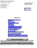


VCR SAFETY NOTES
FIRE & SHOCK HAZARD (VCR)
1. Be sure that all components are positioned in such a way to avoid possibility of shorts to adjacent
components. This is especially important on those chassis which are transported to and from the repair
shop.
2. Always replace all protective devices such as insulators and barriers after working on a set.
3. Check for damaged insulation on wires including the ac cord.
4. Check across-the-line components for damage and replace if necessary.
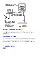
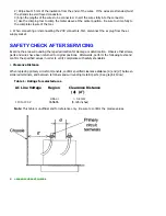
5. After re-assembly of the unit, always perform an ac leakage test on the exposed metallic parts of the
cabinet such as the knobs, antenna terminals, etc. to be sure the set is safe to operate without danger of
electrical shock.
Do not use a line isolation transformer during this test.
Use an ac voltmeter
having 5000 ohms per volt or more sensitivity in the following manner: Connect a 1500 ohm 10 wan
resistor, paralleled by 0.15 MFD ac type capacitor, between a known good earth ground (water pipe,
conduit, etc.) and the exposed metallic parts, one at a time. Measure the ac voltage across the
combination 1500 ohm resistor and 0.15 MFD capacitor. Reverse the ac plug on the set and repeat ac
voltage measurements again for each exposed metallic part. Voltage measured must not exceed O.6
volts R.M.S. This corresponds to 0.4 milliamp ac. Any value exceeding this limit constitutes a potential
shock hazard and must be corrected immediately.
GENERAL
Power Supply-This receiver is designed for operation on 120 Volts, 6OHz alternating current (ac) only.
Never connect to a supply having a different frequency or voltage.
IMPORTANT NOTICE
This device employs many circuits, components, and mechanical parts designed for protection against
fire, shock and RF interference. For continued safety any servicing should be performed by qualified
personnel and exact replacement parts should be used. Under no circumstances should the original
design be altered.
PRODUCT SAFETY GUIDELINES FOR ALL PRODUCTS
CAUTION
: Do not modify any circuit. Service work should be performed only after you are thoroughly
familiar with all of the following safety checks. Risk of potential hazards and injury to the user increases if
safety checks are not adhered to.
USE A SEPARATE ISOLATION TRANSFORMER FOR THIS UNIT WHEN SERVICING.
Summary of Contents for 55PL9524/37
Page 10: ...Page 9 of 15 2004 08 09 ...
Page 23: ...Display The Main Cabinet Exploded View ...
Page 34: ......
Page 35: ......
Page 36: ......
Page 37: ...IIC BUS SIGNAL DIAGRAM ...
Page 39: ......
Page 40: ......
Page 41: ......
Page 42: ......
Page 43: ......
Page 44: ......
Page 45: ......
Page 46: ......
Page 47: ......
Page 48: ......
Page 49: ......
Page 50: ......
Page 51: ......
Page 52: ......
Page 53: ......
Page 54: ......
Page 55: ......
Page 56: ......
Page 57: ......
Page 58: ......
Page 59: ......
Page 60: ......
Page 61: ......
Page 62: ......
Page 63: ......
Page 64: ......
Page 65: ......
Page 66: ......
Page 67: ......
Page 68: ......
Page 69: ......
Page 70: ......
Page 71: ......
Page 72: ......
Page 73: ......
Page 74: ......
Page 75: ......
Page 76: ......
Page 77: ......
Page 78: ......
Page 79: ......
Page 80: ......
Page 81: ......
Page 82: ......
Page 83: ......
Page 84: ......
Page 87: ... W INPUT POWER PANEL Bottom View Return to Circuit Board TOC ...
Page 89: ... U1 MAIN POWER PANEL Bottom View Return to Circuit Board TOC ...
Page 91: ... K SYSTEM BOARD Bottom View Return to Circuit Board TOC ...
Page 92: ...Refer to the next page for Bottom Side View B SSB PANEL Top View Return to Circuit Board TOC ...
Page 93: ... B SSB PANEL Bottom View Return to Circuit Board TOC ...
Page 95: ... SL SCALER PANEL Bottom View Return to Circuit Board TOC ...
Page 97: ... F DW PIP PANEL Bottom View Return to Circuit Board TOC ...
Page 99: ... CB1 3D COMB FILTER PANEL Bottom View Return to Circuit Board TOC ...
Page 101: ... V REAR JACK PANEL Bottom View Return to Circuit Board TOC ...
Page 103: ... O1 SIDE JACK PANEL Bottom View Return to Circuit Board TOC ...
Page 105: ... LS LED SENSOR PANEL Bottom View Return to Circuit Board TOC ...
Page 107: ... P1 LED KEYBOARD PANEL Bottom View Return to Circuit Board TOC ...
Page 109: ... TS1 THERMAL SENSOR PANEL Bottom View Return to Circuit Board TOC ...
Page 111: ... AA1 AUDIO AMPLIFIER PANEL Bottom View Return to Circuit Board TOC ...
Page 112: ...Refer to the next page for Bottom Side View Return to Circuit Board TOC ...
Page 113: ...Return to Circuit Board TOC ...
Page 115: ... 7665 Page 1 P1 P2 P3 P4 P5 P6 P7 C1 C2 C3 C4 C5 C6 F30 F31 F32 L14 L15 L16 V31 ...
Page 116: ... 7665 Page 2 V32 F14 I 6 L 8 V 1 V 2 V 6 V 7 V 8 V 9 V10 L1 L2 L3 L4 L5 L6 L7 L8 L9 ...
Page 117: ... 7665 Page 3 F17 F18 F19 F20 L12 V19 V20 V21 V28 V29 V30 B51 B52 B53 B54 B55 B57 B58 B60 A15 ...
Page 121: ... 7665 Page 7 F2 F14 F15 F16 F17 F18 V19A V20A F 3 F 4 F 5 F 6 F 7 F 8 F 9 F10 F11 F12 F13 A1 ...
Page 122: ... 7665 Page 8 A2 A3 A4 A5 A6 A7 A8 ...
Page 124: ...Overall Cabinet Exploded View Page 1 of 5 ...
Page 125: ...Cabinet Detail 1 Exploded View Page 2 of 5 ...
Page 126: ...Cabinet Detail 2 Exploded View Page 3 of 5 ...
Page 127: ...Power Supply Assembly Exploded View Page 4 of 5 ...