


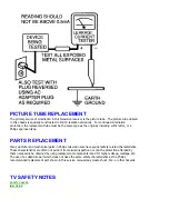


LEAKAGE CURRENT HOT CHECK
1. Do not use an isolation transformer for this test. Plug the completely reassembled receiver directly
into the ac outlet.
2. Connect a
1.5k, 1OW resistor
paralleled by a
0.15uF. capacitor
between each exposed
metallic cabinet part and a
good earth ground
such as a water pipe, as shown below.
3. Use an ac voltmeter with at least 5000 ohms/volt sensitivity to measure the potential across the
resistor.
4.
The potential at any point should not exceed 0.75 volts
.
A leakage current tester may be
used to make this test; leakage current must not exceed 0.5milliamp. If a measurement is outside of the
specified limits, there is a possibility of shock hazard. The receiver should be repaired and rechecked
before returning it to the customer.
5
. Repeat the above procedure with the ac plug reversed.
(Note: An ac adapter is
necessary when a polarized plug is used. Do not defeat the polarizing feature of the plug.)
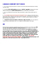
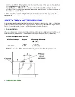
OR
With the instrument completely reassembled, plug the AC line cord directly into a 120V AC outlet.
(Do
not use an isolation transformer during this test.)
Use a leakage current tester or a
metering system that complies with American National Standards Institute (ANSI) C101.1 Leakage
Current for Appliances and Underwriters Laboratories (UL) 1410, (50.7).
With the instrument
AC switch first in the on position and then in the off position, measure from a
known earth ground (metal water pipe, conduit, etc.) to all exposed metal
parts of the instrument (antennas, handle brackets, metal cabinet, screw
heads, metallic overlays, control shafts, etc.), especially any exposed metal
parts that offer an electrical return path to the chassis.
Any current
measured must not exceed 0.5 milliamp.
Reverse the instrument power cord
plug in the outlet and repeat the test. See graphic below.
Summary of Contents for 55PL9524/37
Page 10: ...Page 9 of 15 2004 08 09 ...
Page 23: ...Display The Main Cabinet Exploded View ...
Page 34: ......
Page 35: ......
Page 36: ......
Page 37: ...IIC BUS SIGNAL DIAGRAM ...
Page 39: ......
Page 40: ......
Page 41: ......
Page 42: ......
Page 43: ......
Page 44: ......
Page 45: ......
Page 46: ......
Page 47: ......
Page 48: ......
Page 49: ......
Page 50: ......
Page 51: ......
Page 52: ......
Page 53: ......
Page 54: ......
Page 55: ......
Page 56: ......
Page 57: ......
Page 58: ......
Page 59: ......
Page 60: ......
Page 61: ......
Page 62: ......
Page 63: ......
Page 64: ......
Page 65: ......
Page 66: ......
Page 67: ......
Page 68: ......
Page 69: ......
Page 70: ......
Page 71: ......
Page 72: ......
Page 73: ......
Page 74: ......
Page 75: ......
Page 76: ......
Page 77: ......
Page 78: ......
Page 79: ......
Page 80: ......
Page 81: ......
Page 82: ......
Page 83: ......
Page 84: ......
Page 87: ... W INPUT POWER PANEL Bottom View Return to Circuit Board TOC ...
Page 89: ... U1 MAIN POWER PANEL Bottom View Return to Circuit Board TOC ...
Page 91: ... K SYSTEM BOARD Bottom View Return to Circuit Board TOC ...
Page 92: ...Refer to the next page for Bottom Side View B SSB PANEL Top View Return to Circuit Board TOC ...
Page 93: ... B SSB PANEL Bottom View Return to Circuit Board TOC ...
Page 95: ... SL SCALER PANEL Bottom View Return to Circuit Board TOC ...
Page 97: ... F DW PIP PANEL Bottom View Return to Circuit Board TOC ...
Page 99: ... CB1 3D COMB FILTER PANEL Bottom View Return to Circuit Board TOC ...
Page 101: ... V REAR JACK PANEL Bottom View Return to Circuit Board TOC ...
Page 103: ... O1 SIDE JACK PANEL Bottom View Return to Circuit Board TOC ...
Page 105: ... LS LED SENSOR PANEL Bottom View Return to Circuit Board TOC ...
Page 107: ... P1 LED KEYBOARD PANEL Bottom View Return to Circuit Board TOC ...
Page 109: ... TS1 THERMAL SENSOR PANEL Bottom View Return to Circuit Board TOC ...
Page 111: ... AA1 AUDIO AMPLIFIER PANEL Bottom View Return to Circuit Board TOC ...
Page 112: ...Refer to the next page for Bottom Side View Return to Circuit Board TOC ...
Page 113: ...Return to Circuit Board TOC ...
Page 115: ... 7665 Page 1 P1 P2 P3 P4 P5 P6 P7 C1 C2 C3 C4 C5 C6 F30 F31 F32 L14 L15 L16 V31 ...
Page 116: ... 7665 Page 2 V32 F14 I 6 L 8 V 1 V 2 V 6 V 7 V 8 V 9 V10 L1 L2 L3 L4 L5 L6 L7 L8 L9 ...
Page 117: ... 7665 Page 3 F17 F18 F19 F20 L12 V19 V20 V21 V28 V29 V30 B51 B52 B53 B54 B55 B57 B58 B60 A15 ...
Page 121: ... 7665 Page 7 F2 F14 F15 F16 F17 F18 V19A V20A F 3 F 4 F 5 F 6 F 7 F 8 F 9 F10 F11 F12 F13 A1 ...
Page 122: ... 7665 Page 8 A2 A3 A4 A5 A6 A7 A8 ...
Page 124: ...Overall Cabinet Exploded View Page 1 of 5 ...
Page 125: ...Cabinet Detail 1 Exploded View Page 2 of 5 ...
Page 126: ...Cabinet Detail 2 Exploded View Page 3 of 5 ...
Page 127: ...Power Supply Assembly Exploded View Page 4 of 5 ...