


GENERAL SAFETY NOTES
IMPORTANT SAFETY NOTICE
Proper service and repair is important to the safe, reliable operation of all Philips Consumer Electronics
Company** equipment. The service procedures recommended by Philips and described in this service
manual are effective methods of performing service operations. Some of these service operations require
the use of tools specially designed for the purpose. The special tools should be used when and as
recommended.
It is important to note that this manual contains various
CAUTIONS
and
NOTICES
which should be
carefully read in order to minimize the risk of personal injury to service personnel. The possibility exists
that improper service methods may damage the equipment. It also is important to understand that
these
CAUTIONS
and
NOTICES ARE NOT EXHAUSTIVE
. Philips could not possibly know, evaluate
and advise the service trade of all conceivable ways in which service might be done or of the possible
hazardous consequences of each way. Consequently, Philips has not undertaken any such broad
evaluation. Accordingly, a servicer who uses a service procedure or tool which is not recommended by
Philips must first satisfy himself thoroughly that neither his safety nor the safe operation of the
equipment will be jeopardized by the service method selected.
** Hereafter throughout this manual, Philips Consumer Electronics Company will be referred to as
Philips.
WARNING
Critical components having special safety characteristics are identified with a
or
"S"
by the Ref. No.
in the parts list and enclosed within a broken line* (where several critical components are grouped in one
area) along with the safety symbol
on the schematics or exploded views. Use of substitute
replacement parts which do not have the same specified safety characteristics may create shock, fire, or
other hazards. Under no circumstances should the original design be modified or altered without written
permission from Philips. Philips assumes no liability, express or implied, arising out of any unauthorized
modification of design. Servicer assumes all liability.
•
Broken Line
____ _ ____ _ ____ _ ____
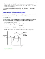
SAFETY CHECKS
After the original service problem has been corrected, a complete safety check should be made. Be sure
to check over the entire set, not just the areas where you have worked. Some previous servicer may
have left an unsafe condition, which could be unknowingly passed on to Your customer. Be sure to
check all of the following:
FIRE AND SHOCK HAZARD
IMPLOSION
X-RADIATION
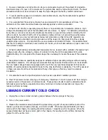
LEAKAGE CURRENT COLD CHECK
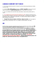
LEAKAGE CURRENT HOT CHECK
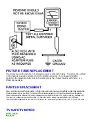
PICTURE TUBE REPLACEMENT
Summary of Contents for 55PL9524/37
Page 10: ...Page 9 of 15 2004 08 09 ...
Page 23: ...Display The Main Cabinet Exploded View ...
Page 34: ......
Page 35: ......
Page 36: ......
Page 37: ...IIC BUS SIGNAL DIAGRAM ...
Page 39: ......
Page 40: ......
Page 41: ......
Page 42: ......
Page 43: ......
Page 44: ......
Page 45: ......
Page 46: ......
Page 47: ......
Page 48: ......
Page 49: ......
Page 50: ......
Page 51: ......
Page 52: ......
Page 53: ......
Page 54: ......
Page 55: ......
Page 56: ......
Page 57: ......
Page 58: ......
Page 59: ......
Page 60: ......
Page 61: ......
Page 62: ......
Page 63: ......
Page 64: ......
Page 65: ......
Page 66: ......
Page 67: ......
Page 68: ......
Page 69: ......
Page 70: ......
Page 71: ......
Page 72: ......
Page 73: ......
Page 74: ......
Page 75: ......
Page 76: ......
Page 77: ......
Page 78: ......
Page 79: ......
Page 80: ......
Page 81: ......
Page 82: ......
Page 83: ......
Page 84: ......
Page 87: ... W INPUT POWER PANEL Bottom View Return to Circuit Board TOC ...
Page 89: ... U1 MAIN POWER PANEL Bottom View Return to Circuit Board TOC ...
Page 91: ... K SYSTEM BOARD Bottom View Return to Circuit Board TOC ...
Page 92: ...Refer to the next page for Bottom Side View B SSB PANEL Top View Return to Circuit Board TOC ...
Page 93: ... B SSB PANEL Bottom View Return to Circuit Board TOC ...
Page 95: ... SL SCALER PANEL Bottom View Return to Circuit Board TOC ...
Page 97: ... F DW PIP PANEL Bottom View Return to Circuit Board TOC ...
Page 99: ... CB1 3D COMB FILTER PANEL Bottom View Return to Circuit Board TOC ...
Page 101: ... V REAR JACK PANEL Bottom View Return to Circuit Board TOC ...
Page 103: ... O1 SIDE JACK PANEL Bottom View Return to Circuit Board TOC ...
Page 105: ... LS LED SENSOR PANEL Bottom View Return to Circuit Board TOC ...
Page 107: ... P1 LED KEYBOARD PANEL Bottom View Return to Circuit Board TOC ...
Page 109: ... TS1 THERMAL SENSOR PANEL Bottom View Return to Circuit Board TOC ...
Page 111: ... AA1 AUDIO AMPLIFIER PANEL Bottom View Return to Circuit Board TOC ...
Page 112: ...Refer to the next page for Bottom Side View Return to Circuit Board TOC ...
Page 113: ...Return to Circuit Board TOC ...
Page 115: ... 7665 Page 1 P1 P2 P3 P4 P5 P6 P7 C1 C2 C3 C4 C5 C6 F30 F31 F32 L14 L15 L16 V31 ...
Page 116: ... 7665 Page 2 V32 F14 I 6 L 8 V 1 V 2 V 6 V 7 V 8 V 9 V10 L1 L2 L3 L4 L5 L6 L7 L8 L9 ...
Page 117: ... 7665 Page 3 F17 F18 F19 F20 L12 V19 V20 V21 V28 V29 V30 B51 B52 B53 B54 B55 B57 B58 B60 A15 ...
Page 121: ... 7665 Page 7 F2 F14 F15 F16 F17 F18 V19A V20A F 3 F 4 F 5 F 6 F 7 F 8 F 9 F10 F11 F12 F13 A1 ...
Page 122: ... 7665 Page 8 A2 A3 A4 A5 A6 A7 A8 ...
Page 124: ...Overall Cabinet Exploded View Page 1 of 5 ...
Page 125: ...Cabinet Detail 1 Exploded View Page 2 of 5 ...
Page 126: ...Cabinet Detail 2 Exploded View Page 3 of 5 ...
Page 127: ...Power Supply Assembly Exploded View Page 4 of 5 ...