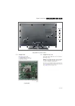


Mechanical Instructions
4.
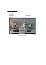
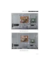
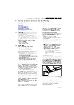
Figure 4-16 Back cover screw positions
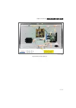
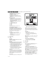
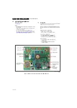
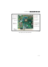
4.3.2
Small Signal Board
Refer to
for details.
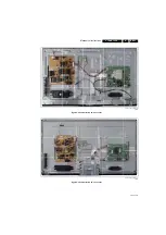
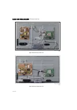
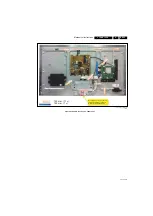
1.
Unplug the LVDS connector [1].
2.
Unplug the remaining connectors [2].
3.
Remove the screws [3].
Figure 4-17 SSB
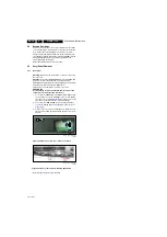
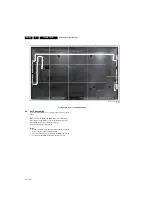
4.3.3
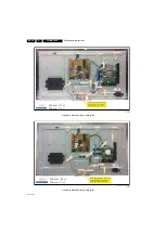
Ambilight units in Rear Cover
The Ambilight units are affixed in the rear cover and will self-
destruct upon removal.
Attention:
it is of the utmost importance to remove all remains
of any adhesive that might be left on the inside of the rear
cover, prior to affixing the new Ambilight units.
The new units come with double-sided adhesive tape. Ensure
a correct mounting to avoid uneven light emission of the units.
Refer to
for the wiring position.
19510_106_1
3
0424.ep
s
1
3
0424
1
M4 × 10
M
3
×
8
1
1
1
1
2
2
2
2
2
2
2
2
2
2
M
3
× 5
3
3
Q
3
× 10
4
4
4
4
4
4
4
4
19510_10
8
_1
3
0424.ep
s
1
3
0424
2
1
3
3
3
3


