background image

The ends of the 3 phases are connected in the star point. The terminal voltage is √3 times the phase 
voltage, the mains current is equal to the phase current. The star circuit is marked with the Y symbol.

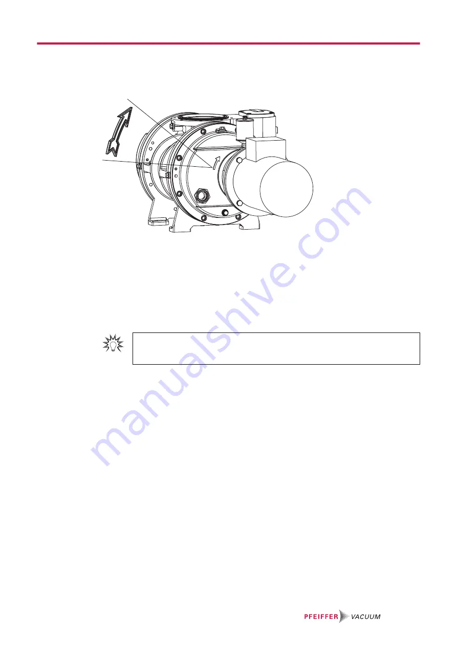
5.6.2 Checking the direction of rotation

Fig. 8:

Check of direction of rotation

Procedure

When switching on for the first time, check the roots pump direction of rotation.

1. Switch the vacuum pump on briefly (2 to 3 seconds)

– The motor and coupling must rotate clockwise (see directional arrow on housing cover).

2. If the direction of rotation is incorrect, exchange the 2 phases on the connection cable.

5.6.3 Connecting the PTC thermistor tripping unit

Tripping units store the shut-down

Pfeiffer Vacuum recommends connecting motors with PTC in the stator winding to a PTC 
resistor tripping device for protection against overload.

Installation 

25/52

Summary of Contents for OKTA 1000

Page 1: ...OPERATING INSTRUCTIONS EN Translation of the Original OKTA 1000 OKTA 1000 M Roots pump...

Page 2: ...eiffer vacuum de Further operating instructions from Pfeiffer Vacuum can be found in the Download Center on our website Disclaimer of liability These operating instructions describe all models and var...

Page 3: ...p 20 5 2 Filling with lubricant 20 5 3 Filling with sealing oil 21 5 4 Connecting vacuum side 22 5 5 Connecting the fore vacuum side 23 5 6 Connect to mains power supply 23 5 6 1 Connecting three phas...

Page 4: ...et of seals for version with magnetic coupling 44 11 3 Maintenance kit for version with RSSR 44 11 4 Maintenance kit for version with magnetic coupling 44 12 Accessories 45 12 1 Accessory information...

Page 5: ...Maintenance intervals 32 Tbl 6 Troubleshooting 41 Tbl 7 Available spare parts packages 44 Tbl 8 Accessories for Okta 1000 Standard M 46 Tbl 9 Consumables 46 Tbl 10 Conversion table Pressure units 47 T...

Page 6: ...ig 6 Delta connection for low voltage 24 Fig 7 Star circuit for high voltage 24 Fig 8 Check of direction of rotation 25 Fig 9 Connection example with PTC thermistor tripping unit 26 Fig 10 Drain the l...

Page 7: ...nts These instructions apply for roots pumps of the following versions Pump type Pump designs Standard ver sion Standard version Standard motor The housing and all parts forming the suction chamber co...

Page 8: ...he stickers on the product along with their meanings Mod Okta 1000 Weight 240 kg 3 D 35641 Asslar Made in Germany Mod No PP W41 n max 4500 1 min Oil P3 2 9 l S N max 1775 m h 02 2019 Ser No 143 Rating...

Page 9: ...on arrow cast in the cover 6 Hot surface warning sign 1 3 4 Abbreviations Abbreviation Explanation OI Operating instructions DIN German Institute for Standardization Deutsches Institut f r Normung E C...

Page 10: ...perty Notes tips or examples indicate important information about the product or about this docu ment 2 2 Safety instructions All safety instructions in this document are based on the results of the r...

Page 11: ...bserve the permissible pressures and pressure differentials for the product Check the function of the exhaust line on a regular basis CAUTION Risk of injury from loss of stability During setup there i...

Page 12: ...and medical implants Make sure that such individuals do not enter the sphere of influence 2 m of the magnetic field Identify rooms in which magnetic couplings are openly accessible with the symbol No...

Page 13: ...he installation operation or maintenance of the product must read understand and adhere to the safety related parts of this document Infringement of conformity due to modifications to the product The...

Page 14: ...ll warranty and liability claims Any use that is counter to the purpose of the product whether intentional or unintentional is regarded as improper use in particular Transport installation or operatio...

Page 15: ...Use of accessories or spare parts not listed in these instructions Using the vacuum pump as a climbing aid Safety 15 52...

Page 16: ...t be operated in conjunction with a backing pump connected upstream Roots pumps of the M series are equipped with a magnetic coupling 1 4 2 3 9 8 10 11 12 14 13 15 5 6 7 Fig 2 Design construction 1 Va...

Page 17: ...00 PN 16 Okta 1000 M pressure surge pro tected Tbl 4 Features of the roots pumps 3 4 Scope of delivery Roots pump Seals for the connection flanges for ISO flanges centering rings are included Cover di...

Page 18: ...nection flange once the pipes have been mounted Fill the gear and bearing chambers with lubricant only once the final installation posi tion is reached Preparations for transport Pfeiffer Vacuum recom...

Page 19: ...n the roots pump interior are provided with corrosion protection Storage Pfeiffer Vacuum recommends storing the products in their original transport packaging Procedure 1 Vacuum seal both connection f...

Page 20: ...using ensure adequate air circulation 6 Keep both sight glasses freely accessible for checks and maintenance 7 Keep the filling drain holes freely accessible 8 Ensure that the motor rating plate remai...

Page 21: ...iller screws Tightening torque 32 Nm 4 Check the fill level during operation in the final vacuum 5 If necessary top up the lubricant only when the roots pump is switched off and vented 5 3 Filling wit...

Page 22: ...otective strainer start up strainer in the intake flange Ensure that this strainer is only removed when the risk of solid particles entering the vacuum pump can be excluded Observe any pumping speed d...

Page 23: ...if necessary 8 If an air trap is created in the system then install a condensate drain facility at the lowest point 5 6 Connect to mains power supply DANGER Danger to life from electric shock Touchin...

Page 24: ...hout switch and mains cable 5 6 1 Connecting three phase motor with 6 pin terminal board NOTICE Property damage from high starting torque The specific load behavior of the vacuum pump requires direct...

Page 25: ...time check the roots pump direction of rotation 1 Switch the vacuum pump on briefly 2 to 3 seconds The motor and coupling must rotate clockwise see directional arrow on housing cover 2 If the directi...

Page 26: ...sensor S1 OFF button H1 Tripping indicator S2 ON button M Motor 3 phase S3 RESET button 1 For devices with two relay outputs only K1 Contactor 2 For MSR type model only F1 F4 Fuses 3 Only for order no...

Page 27: ...on hot surfaces Depending on the operating and ambient conditions the surface temperature of the vacuum pump can increase to above 70 C Provide suitable touch protection Supplementary Information for...

Page 28: ...0 01 AS 0 08 Sth Rated volume flow rate of the roots pump m3 h Procedure Depending on the operating pressure the empirical value for the supplied sealing gas amount is be tween 1 for a high operating...

Page 29: ...e vacuum pump Make sure that the sealing gas pressure inside the pump does not exceed 1200 hPa Stop the sealing gas supply immediately after switching off the vacuum pump Procedure with clean processe...

Page 30: ...f contact being made between the rotor at warm operating temperature and the colder pump housing This will result in irreversible pump damage Avoid uneven cooling if you are going to switch the roots...

Page 31: ...ntentional reactivation 5 Remove the vacuum pump from the system if necessary 6 Dispose of used lubricant according to applicable regulations in each case 7 For maintenance work only dismantle the vac...

Page 32: ...ing agent compatible with the process Changing lubricant and sealing oil Maintenance level 2 Checking coupling for dam age replacing toothed ring if necessary Changing radial shaft seal rings and prot...

Page 33: ...quipment Use a suitable collection receptacle Pfeiffer Vacuum recommends determining the precise service life of the lubricant in the first operating year The usable life may deviate from the referenc...

Page 34: ...page 20 2 Screw in the lubricant filler screws again Tightening torque max 32 Nm 7 4 Changing sealing oil NOTICE Damage to the vacuum pump due to incorrect procedure when filling sealing oil Disassem...

Page 35: ...ng the suction chamber WARNING Risk of crushing from rotating parts Fingers and hands may be caught by rotating pistons within the connection flange This results in se vere injuries Keep limbs out of...

Page 36: ...the guide pins this has an adverse effect on damping If necessary replace completely if there are pronounced traces of wear 7 Clean the other parts 8 Inspect all parts for wear and replace if necessa...

Page 37: ...ead screw with washer and spring washer Tightening torque TP 32 Nm 7 8 Installing the coupling for versions with magnetic coupling WARNING Danger of injury from strong magnetic field There is a risk o...

Page 38: ...Supplementary information for work on the magnetic couplings of Roots pumps Upon request you can obtain supplementary information PW0142 from Pfeiffer Vacuum Download Center Maintenance 38 52...

Page 39: ...nger than 2 years we recommend you carry out maintenance and a lubri cant change prior to recommissioning 12 Please note the vacuum pump may not be stored in the vicinity of machines traffic routes et...

Page 40: ...low the vacuum pump to cool if needed Suction chamber contami nated Clean suction chamber If necessary contact Pfeiffer Vacuum Service Gear gear wheels dam aged Switch off the vacuum pump immedi ately...

Page 41: ...coupling is de stroyed by demagnetiza tion Switch off the vacuum pump immedi ately and wait for it to come to a com plete standstill While the vacuum pump is at a stand still the magnets can realign...

Page 42: ...ity You can find more detailed information and addresses on our homepage in the Pfeiffer Vacuum Service section You can obtain advice on the optimal solution for you from your Pfeiffer Vacuum represen...

Page 43: ...duct in suitable stable transport containers only e Maintain applicable transport conditions ERKL RUNG KONTAMINIERUNG 6 Attach the contamination declaration to the outside of the packag ing 7 Now send...

Page 44: ...ive sleeve and centering rings for connecting the roots pump to the suction and pressure sides are not included 11 2 Set of seals for version with magnetic coupling The set of seals contains all seali...

Page 45: ...0 M Okta 600 M Okta 800 M Okta 1000 M Okta 2000 M Okta 4000 M Okta 6000 M G 1 1 4 PK 005 639 U Sealing gas kit plastic tube for Okta 250 M Okta 300 M Okta 500 M Okta 600 M Okta 800 M Okta 1000 M Okta...

Page 46: ...I with PV 24 V DC 310VEP160 02 OmniControl 200 with TPR 270 PT 440 950 T Frequency converter Okta 1000 M installed in the control cabinet PP 078 300 AT Oil compensating line with oil level monitoring...

Page 47: ...0 1 59 2 0 75 0 987 Pa m3 s 10 1 592 7 5 9 87 sccm 1 69 10 2 1 69 10 3 1 1 27 10 2 1 67 10 2 Torr l s 1 33 0 133 78 9 1 1 32 atm cm3 s 1 01 0 101 59 8 0 76 1 Tbl 11 Conversion table Units for gas thr...

Page 48: ...tor protection 3TF 3TF Pumping speed category 1000 m3 h 1000 m3 h Operating fluid amount 2 9 l 2 9 l DN 1 DN 160 ISO F DN 160 ISO F DN 2 DN 100 ISO F DN 100 ISO F DN 3 DN 100 ISO F DN 100 ISO F Ambien...

Page 49: ...us substances 2011 65 EU Restriction of the use of certain hazardous substances delegated directive 2015 863 EU Harmonized standards and applied national standards and specifications DIN EN ISO 12100...

Page 50: ...ction of the Use of Certain Hazardous Substances in Electrical and Elec tronic Equipment Regulations 2012 Harmonized standards and applied national standards and specifications ISO 12100 2010 EN ISO 2...

Page 51: ...51 52...

Page 52: ...PP0950 ed T Date 2211 P N PP0950BEN...

Reviews: