background image

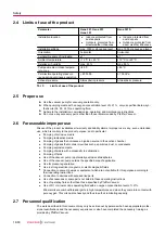
2.4 Limits of use of the product

Parameter

Hena 201, Hena 251,
Hena 301

Hena 301 S

Installation location

● Indoors, protected from 

dust deposits

● Outdoors, protected from 

direct weather influences

● Indoors, protected from 

dust deposits

● Outdoors, protected from 

direct weather influences

Installation altitude

max. 1000 m above sea level

max. 1000 m above sea level

Orientation

horizontal

horizontal

permissible angle of inclination

±1 °

±1 °

Ambient temperature

+12 °C to +40 °C

+12 °C to +40 °C

Relative air humidity

max. 85 %

max. 85 %

Pumped medium intake tempera-

ture, max.

+80 °C

+80 °C

Permissible operating pressure 

range during continuous operation

< 800 hPa

≤ 100 hPa

Exhaust pressure

Atmospheric pressure

Atmospheric pressure

Tbl. 3:

Limits of use of the product

2.5 Proper use

► Use the vacuum pump for vacuum generation only.
► When pumping media with an oxygen concentration level of ≥ 21 %, only use perfluorinated, syn-

thetic oils (F4, F5, A113) as operating fluid.

► Adhere to the installation, commissioning, operating, and maintenance instructions.
► Do not use any accessory parts other than those recommended by Pfeiffer Vacuum.

2.6 Foreseeable improper use

Misuse of the product invalidates all warranty and liability claims. Improper use is any, even unintended, 
use, which is contrary to the product purpose; and in particular:

● Pumping of corrosive media
● Pumping radioactive media
● Pumping of gases that introduce an ignition source to the suction chamber
● Pumping of gases that contain impurities such as particles, dust, or condensate
● Pumping explosive media
● Pumping of media with a propensity to sublimation
● Pumping of fluids
● Use of the vacuum pump in potentially explosive atmospheres
● Use of the vacuum pump outside the specified area of application
● Use for pressure generation
● Use in strong electrical, magnetic, or electromagnetic fields
● Connection to vacuum pumps or equipment which are not suitable for this purpose according to 

their operating instructions

● Connection to devices with exposed live parts
● Use of accessories or spare parts not listed in these operating instructions
● Use of operating fluids other than those specified by Pfeiffer Vacuum
● Use of D1 or mineral oil as operating fluid with an oxygen concentration level of > 21%

Mineral oils are combustible and ignite in high temperatures and when they come into contact with 
pure oxygen. This oils oxidize heavily and thus lose their lubricating capacity.

2.7 Personnel qualification

The work described in this document may only be carried out by persons who have appropriate profes-
sional qualifications and the necessary experience or who have completed the necessary training as 
provided by Pfeiffer Vacuum.

Safety

14/60

Summary of Contents for HENA 201

Page 1: ...OPERATING INSTRUCTIONS EN Translation of the Original HENA 201 251 301 301 S Rotary vane pump ...

Page 2: ...feiffer vacuum de Further operating instructions from Pfeiffer Vacuum can be found in the Download Center on our website Disclaimer of liability These operating instructions describe all models and variants of your product Note that your product may not be equipped with all features described in this document Pfeiffer Vacuum constantly adapts its products to the latest state of the art without pri...

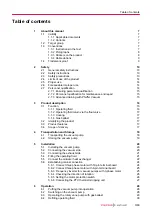
Page 3: ... 1 4 Gas ballast 17 3 2 Identifying the product 17 3 3 Product features 17 3 4 Scope of delivery 17 4 Transportation and Storage 18 4 1 Transporting the vacuum pump 18 4 2 Storing the vacuum pump 19 5 Installation 20 5 1 Installing the vacuum pump 20 5 2 Connecting the vacuum side 20 5 3 Connecting the exhaust side 21 5 4 Filling the operating fluid 21 5 5 Connect the oil water heat exchanger 22 5...

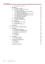
Page 4: ...rainer 40 7 6 Cleaning the gas ballast filter 40 7 7 Changing the operating fluid type 41 8 Decommissioning 42 8 1 Shutting down for longer periods 42 8 2 Recommissioning 42 8 3 Disposing of the vacuum pump 42 9 Malfunctions 43 10 Service solutions from Pfeiffer Vacuum 45 11 Spare parts 47 11 1 Ordering spare parts packs 47 11 2 Operating fluids Maintenance level 1 47 11 3 Maintenance kit maintena...

Page 5: ...rotection switch setting values for Hena 251 Hena 301 from index A 26 Tbl 8 Maintenance intervals 33 Tbl 9 Troubleshooting for rotary vane pumps 44 Tbl 10 Spare parts packages Hena 201 47 Tbl 11 Spare parts packages Hena 251 Hena 301 Hena 301 S 47 Tbl 12 Consumables 47 Tbl 13 Accessories 49 Tbl 14 Consumables 49 Tbl 15 Conversion table Pressure units 50 Tbl 16 Conversion table Units for gas throug...

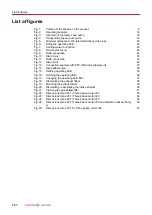
Page 6: ...PTC thermistor tripping unit 27 Fig 14 Gas ballast valve 30 Fig 15 Refilling operating fluid 30 Fig 16 Draining the operating fluid 36 Fig 17 Changing the operating fluid filter 37 Fig 18 Dismantling the exhaust filters 38 Fig 19 Mounting the exhaust filters 39 Fig 20 Dismantling assembling the intake strainer 40 Fig 21 Cleaning the gas ballast filter 41 Fig 22 Dimensions Hena 201 Three phase moto...

Page 7: ...tandard version of rotary vane pump Hena 251 Standard version of rotary vane pump Hena 301 Standard version of rotary vane pump Rotary vane pump with water cooling Hena 301 S Rotary vane pump with limited intake pressure 1 2 Target group These operating instructions are aimed at all persons performing the following activities on the product Transportation Setup Installation Usage and operation Dec...

Page 8: ...ting plate of the rotary vane vacuum pump Motor rating plate not shown Warning hot surface This sticker warns of injuries caused by high temperatures in case of touching without protection during operation Operating instructions note This sticker indicates that this operating instructions must be read before per forming any tasks Arrow indicating direction of rotation The direction of rotation arr...

Page 9: ...class N N Mean sea level PE Earthed conductor protective earth PTC Temperature dependent resistor positive temperature coefficient PVC Polyvinyl chloride PVC WAF width across flats RSSR Radial shaft seal ring MM Maintenance manual Tbl 2 Abbreviations used in this document 1 4 Trademark proof Loctite is a trademark of HENKEL IP HOLDING GMBH About this manual 9 60 ...

Page 10: ...mage Notes tips or examples indicate important information on the product or on this document 2 2 Safety instructions All safety instructions in this document are based on the results of the risk assessment carried out in accordance with Machinery Directive 2006 42 EC Annex I and DIN EN ISO 12100 Section 5 Where ap plicable all life cycle phases of the product were taken into account Risks during ...

Page 11: ...oxic process media Observe the pertinent regulations for handling toxic process media Safely purge toxic process media via an exhaust line Use appropriate filter equipment to separate toxic process media WARNING Risk of burns from ejected hot oil mist During operation hot pressurized oil mist escapes from the operating fluid separator Only operate the vacuum pump with the filler screw securely fit...

Page 12: ...om toxic contaminated operating fluid Toxic process media can cause operating fluid contamination When changing the operating fluid there is a health hazard due to contact with poisonous substances Illegal disposal of toxic substan ces causes environmental damage Wear suitable personal protective equipment when handling these media Dispose of the operating fluid according to locally applicable reg...

Page 13: ...tenance of the product must read understand and adhere to the safety related parts of this document Infringement of conformity due to modifications to the product The Declaration of Conformity from the manufacturer is no longer valid if the operator changes the original product or installs additional equipment Following the installation into a system the operator is required to check and re evalu ...

Page 14: ...se which is contrary to the product purpose and in particular Pumping of corrosive media Pumping radioactive media Pumping of gases that introduce an ignition source to the suction chamber Pumping of gases that contain impurities such as particles dust or condensate Pumping explosive media Pumping of media with a propensity to sublimation Pumping of fluids Use of the vacuum pump in potentially exp...

Page 15: ...engineering field in accordance with nationally applicable regulations Knowledge of this documentation In addition these individuals must be familiar with applicable safety regulations and laws as well as the other standards guidelines and laws referred to in this documentation The above individuals must have an explicitly granted operational authorization to commission program configure mark and ...

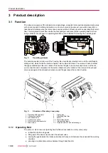
Page 16: ...ically as the rotor rotates This causes the gas to be continuously drawn in at the vac uum connection and compressed in the suction chamber by the rotation of the rotor until the exhaust valve opens against the atmospheric pressure and the gas leaves the suction chamber 1 2 3 4 5 6 7 8 12 11 10 9 Fig 3 Structure of the rotary vane pump 1 Operating fluid separator 7 Sight glass 2 Vacuum connection ...

Page 17: ... exchanger optional 3 1 4 Gas ballast An integrated gas ballast system serves the controlled supply of ambient air or inert gas into the suction chamber Gas ballast supports the reduction of condensate accumulating in the pumping system 3 2 Identifying the product To ensure clear identification of the product when communicating with Pfeiffer Vacuum always keep all of the information on the rating ...

Page 18: ...ontally or without operating fluid filling Fill in the operating fluid only at the final installation location Pfeiffer Vacuum recommends keeping the transport packaging and original protective cov er General information regarding safe transport 1 Observe the weight specified on packaging 2 Use personal protective equipment e g safety shoes 3 Use transport equipment e g fork lift truck or lift tru...

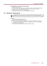
Page 19: ...ly sized level surface 4 2 Storing the vacuum pump Pfeiffer Vacuum recommends storing the products in their original transport packaging Procedure 1 Seal the vacuum and exhaust connection 2 Make sure that the gas ballast valve is closed 3 Store the vacuum pump only in dry dust free rooms within the specified ambient conditions 4 In rooms with humid or aggressive atmospheres Hermetically seal the v...

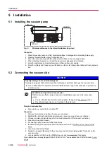
Page 20: ...pump Installation and operation of accessories Pfeiffer Vacuum offers a series of special compatible accessories for its rotary vane pumps You can find information and ordering options for approved accessories online Described accessories are not included in the shipment Required consumables Screw lock e g Loctite 245 or Loctite 577 Procedure 1 Remove the protective cap from the vacuum connection ...

Page 21: ...iping downwards from the vacuum pump to prevent condensate return 4 Clean the connection threads 5 Install the piping with pipe components and fasteners from the Pfeiffer Vacuum Components Shop 6 Use screw lock for the thread 7 Support or suspend the piping to the vacuum pump so that no piping system forces act on the vacuum pump 8 Use a separator or filter from the Pfeiffer Vacuum line of accesso...

Page 22: ... the operating fluid has accumulated in the operating fluid separator 9 Check the fill level The correct fill level is between the Min Max markings or within the ring mark on the sight glass 10 If necessary fill more operating fluid in case the fill level is incorrect 5 5 Connect the oil water heat exchanger NOTICE Vacuum pump damage caused by different cooling characteristics For applications wit...

Page 23: ...article size max 150 µm Cooling water temperature see Technical data Cooling water flow see Technical data Feed line overpressure max 6000 hPa Tbl 5 Requirements on the cooling water composition Required material Cooling water hose ID 19 mm Hose clamps 1 2 3 Fig 7 Cooling water connection 1 Cooling water outlet 3 Oil water heat exchanger 2 Cooling water inlet Making the cooling water connection 1 ...

Page 24: ...ions Route the mains connection in accordance with locally applicable provisions Always provide a suitable mains fuse to protect the motor and supply cable in the event of a fault Pfeiffer Vacuum recommends the circuit breaker type K with slow tripping characteristic NOTICE Property damage from high starting torque The specific load behavior of the vacuum pump requires direct on line starting at f...

Page 25: ...is marked with the symbol The voltage between the incoming mains supply lines is called mains voltage The mains current is the current flowing in the incoming supply lines Star circuit Connect the three phase motor with delta connection Connect the three phase motor according to the connection diagram V L1 L2 L3 W2 U1 U2 V2 V1 W1 Fig 12 Star circuit The ends of the 3 phases are connected in the st...

Page 26: ...he rated current over a 2 minute period is permissible for the drive motors in accordance with EN 60034 1 without tripping the motor protection switch Procedure 1 Take the settings for the motor protection switch from the following table 2 Take into consideration that certain operating conditions for example cold vacuum pump start can cause short term increases in current consumption 3 Set the des...

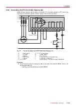
Page 27: ... 2 1 1 1 T1 T3 3 Fig 13 Connection example with PTC thermistor tripping unit US Control voltage T1 T3 PTC resistor sensor S1 OFF button H1 Tripping indicator S2 ON button M Motor 3 phase S3 RESET button 1 For devices with two relay outputs only K1 Contactor 2 For MSR type model only F1 F4 Fuses 3 Only for order no P 4768 052 FQ and P 4768 052 FE Procedure After shut down switch the tripping unit b...

Page 28: ...eck the operating fluid in the sight glass 2 Compare the voltage and frequency specifications on the motor rating plate with the available mains voltage and frequency 3 Protect the vacuum pump from sucking in contamination using suitable measures 4 Check the operating fluid at regular intervals 5 Check the exhaust connection for free passage max permissible pressure atmospheric pres sure 6 Actuate...

Page 29: ...ve 3 Allow the vacuum pump to warm up prior to process start with the vacuum connection closed for approx 30 minutes Inspect operating fluid level 1 Regularly check the operating fluid level while the vacuum pump is running and at operating tem perature 2 Make sure that the fill level is within the markings of the sight glass 3 Check the operating fluid fill level daily during continuous operation...

Page 30: ...as ballast valve to the I position Close gas ballast valve To close turn the screw on the gas ballast valve to the position 0 6 4 Refilling operating fluid Required consumables Operating fluid of the vacuum pump Required aids Funnel optional Refill during operation Operating fluid can be refilled during operation in the final vacuum MAX MIN 1 3 4 2 Max Min Fig 15 Refilling operating fluid 1 Filler...

Page 31: ...ng fluid backflow After the vacuum pump is switched off there is a risk that the connected vacuum system can become contaminated by backflow Vent the vacuum chamber regardless of its size within 30 seconds Shut off the intake line with an additional shut off valve after the vacuum pump is switched off during longer venting operations Rotary vane vacuum pumps of the HenaLine have an integrated non ...

Page 32: ...ge for which Pfeiffer Vacuum accepts no liability We recommend taking advantage of our service training offering When ordering spare parts specify the information on the nameplate The following section describes the tasks for cleaning and maintaining the vacuum pump More ad vanced works are described in the service instructions Prerequisites Vacuum pump switched off Vacuum pump vented to atmospher...

Page 33: ...tenance level 1 operating fluid replacement Clean the outside of the pump housing Clean motor fan cap Changing the operating flu id Changing the operating flu id filter Dismantle and clean the fil ter of the gas ballast valve Operating flu id Operating flu id filter Maintenance level 2 maintenance Change the exhaust filter Clean the operating fluid separator and change the seals Changing the opera...

Page 34: ...rent operating fluid type Safety data sheets You can obtain the safety data sheets for operating fluids from Pfeiffer Vacuum on request or from the Pfeiffer Vacuum Download Center The usable life of operating fluid is dependent on the area of application of the rotary vane vacuum pumps Instructions for when operating fluid should be changed The vacuum pump does not reach the specified ultimate pre...

Page 35: ...s a health hazard due to contact with poisonous substances Illegal disposal of toxic substan ces causes environmental damage Wear suitable personal protective equipment when handling these media Dispose of the operating fluid according to locally applicable regulations CAUTION Scalding from hot operating fluid Danger of burns when draining operating fluid if it comes into contact with the skin Wea...

Page 36: ...careful with the O ring 7 3 3 Rinsing and cleaning the rotary vane vacuum pump Cleaning by changing the operating fluid Pfeiffer Vacuum recommends in cases of heavy contamination with process residues cleaning the inside of the vacuum pump with several operating fluid changes Prerequisites Fresh operating fluid filled Required aids Collection receptacle 7 l Change operating fluid for cleaning 1 Op...

Page 37: ...ptacle below the operating fluid filter 2 Unscrew the operating fluid filter using a strap wrench Pay attention to escaping operating fluid 3 Apply oil to the sealing surface of the operating fluid filter 4 Screw the operating fluid filter on finger tight 7 4 Change the exhaust filter in the operating fluid separator WARNING Health hazard through poisoning from toxic contaminated components or dev...

Page 38: ... Dismantling the exhaust filters Prerequisites Vacuum pump switched off Vacuum pump vented to atmospheric pressure Vacuum pump cooled Required tools Socket key WAF 13 Allen key WAF 6 8x 1 2 4 3 5 6 7 8 Fig 18 Dismantling the exhaust filters 1 Separator cover plate 5 Filter unit 2 Flat seal 6 Operating fluid separator 3 Fixing bolts 7 Exhaust filter 4 Filter material 8 Clamping plate Procedure 1 Re...

Page 39: ...xhaust filter 5 Filter material 1 1 O ring 6 Fixing bolts 2 Clamping plate 7 Flat seal 3 Filter unit 8 Separator cover plate 3 1 O ring 9 Screws 4 Operating fluid separator Procedure 1 Place the new O ring on the front side of the exhaust filters 2 Mount the exhaust filters using the clamping plate The installation orientation is identifiable by an arrow on the filter The arrow must point upwards ...

Page 40: ...mantling the intake strainer 1 Dismantle the operating fluid return line from the vacuum connection 2 Unscrew the cheesehead screws 3 Remove the vacuum connection Pay attention to the washers 4 Remove the intake strainer from the intake duct 5 Dismantle the part of the non return valve resting in the intake duct Clean all parts and examine for wear 1 Clean all parts 2 Examine all parts for wear As...

Page 41: ...e is clogged 7 7 Changing the operating fluid type Possibilities for changing the operating fluid type The operating fluid type can be changed between mineral operating fluid P3 and syn thetic operating fluid D1 only It is not possible to change from P3 D1 to F4 F5 or vice versa Required consumables 3 times the filling quantity of the new operating fluid Changing the operating fluid type 1 Change ...

Page 42: ...g the operating fluid again prior to recommissioning 8 2 Recommissioning NOTICE Risk of damage to vacuum pump as a result of operating fluid aging The operating fluid usability is limited max 2 years Prior to recommissioning following a shutdown of 2 years or more carry out the following work Change the operating fluid Change the radial shaft seal rings and other elastomer parts if required Observ...

Page 43: ...he nameplate Should malfunctions occur you can find information about potential causes and how to fix them here Problem Possible causes Remedy Vacuum pump will not start up No mains voltage or voltage does not corre spond to the motor data Check the mains voltage and mains fuse Check the motor switch Pump temperature too low Check the mains voltage and mains fuse Check the motor switch Thermal pro...

Page 44: ... of vacuum pump too low The intake line is not suitably dimensioned Make sure that connections are short and cross sections ade quately dimensioned Exhaust pressure too high Check exhaust line outlet open ings and exhaust side accesso ries Loss of operating fluid Operating fluid separa tor leaking Check for leaks Replace the seal as required Radial shaft seal rings RSSR leaking 1 Check the RSSR 2 ...

Page 45: ... and addresses can be found on our website in the Pfeiff er Vacuum Service section Advice on the optimum solution is available from your Pfeiffer Vacuum contact partner For quick and smooth handling of the service process we recommend the following steps 1 Download the current form templates Declaration of Service Request Service Request Declaration of Contamination a Dismantle all accessories and...

Page 46: ...containers e Observe the applicable transport conditions ERKLÄRUNG KONTAMINIERUNG 6 Affix the declaration of contamination to the outside of the packag ing 7 Then send your product to your local Service Center 8 You will receive a confirmation message a quotation from Pfeiff er Vacuum For all service orders our General Terms and Conditions of Sales and Supply and General Terms and Conditions of Re...

Page 47: ...f vanes PK E68 025 T Coupling set PK E63 000 T Operating fluid filter P 0920 591 E Gas ballast filter PK 100 171 U Manometer 0 1 bar PK 100 127 Tbl 11 Spare parts packages Hena 251 Hena 301 Hena 301 S 11 2 Operating fluids Maintenance level 1 Select the respective operating fluid type and quantity under consideration of the details on the rating plate Description Order number P3 mineral oil 1 l PK...

Page 48: ...Set of seals with all seals relevant for the function Bearing Intake strainer Operating fluid and exhaust filters Wearing parts of the valves Coupling sleeve 11 5 Set of seals The set of seals contains all seals from the main and sub assemblies Radial shaft seal rings RSSR 11 6 Set of vanes The set of vanes contains Vane 11 7 Coupling set The coupling set contains two coupling halves Coupling slee...

Page 49: ...ering accessories Description Order number Operating Fluid Level Switch PK 100 116 Operating Fluid Temperature Switch PK 100 125 KAS 63 Condensate Separator PK Z10 010 FAK 063 Activated Carbon Filter PK Z30 010 SAS 63 DN 63 ISO K PK Z60 511 Screw in flange DN 100 ISO K G 2 PK 100 058 Screw in flange DN 63 ISO K G 2 PK 100 059 Magnetic Gas Ballast Valve 24 V DC PK 100 145 U PTC Resistor Tripping De...

Page 50: ...1 592 7 5 9 87 sccm 1 69 10 2 1 69 10 3 1 1 27 10 2 1 67 10 2 Torr l s 1 33 0 133 78 9 1 1 32 atm cm3 s 1 01 0 101 59 8 0 76 1 Tbl 16 Conversion table Units for gas throughput 13 2 Technical data Classification Hena 201 Hena 251 Order number PK D03 400 PK D03 432 Connection Atmospheric side Female thread G 2 Female thread G 2 Connection Vacuum side Female thread G 2 Female thread G 2 Nominal pumpi...

Page 51: ...ed No No Weight 182 kg 227 kg Tbl 17 Technical data Hena 201 Hena 251 Classification Hena 301 Hena 301 S Hena 301 Order number PK D03 450 PK D03 455 PK D03 461 Connection At mospheric side Female thread G 2 Female thread G 2 Female thread G 2 Connection Vac uum side Female thread G 2 Female thread G 2 Female thread G 2 Nominal pumping speed at 50 Hz 300 m h 300 m h 300 m h Nominal pumping speed at...

Page 52: ... C 25 55 C 25 55 C Motor version 3 ph motor 3 ph motor 3 ph motor Mains require ment voltage 50 Hz 190 200 220 230 380 400 V 190 200 220 230 380 400 V 190 200 220 230 380 400 V Mains require ment voltage 60 Hz 208 220 230 440 460 V 208 220 230 440 460 V 208 220 230 440 460 V Mains require ment voltage range 5 5 5 Rated power 50 Hz 7 5 kW 7 5 kW 7 5 kW Rated power 60 Hz 9 2 kW 9 2 kW 9 2 kW Rotatio...

Page 53: ...5 315 4 x M10 2 1 5 1 5 1 5 1 5 2 972 253 Ø 50 410 18 G 2 DIN ISO 228 1 0 133 256 5 263 390 263 40 4 x M10 4 x Ø 50 418 2 G 2 DIN ISO 228 1 Fig 22 Dimensions Hena 201 Three phase motor IE3 Technical data and dimensions 53 60 ...

Page 54: ...51 564 180 410 303 418 2 2 1 5 1 5 2 390 298 351 1 5 364 2 1 5 1072 4 x M10 4 x Ø 50 G 2 DIN ISO 228 1 G 2 DIN ISO 228 1 128 257 Fig 23 Dimensions Hena 251 Three phase motor IE3 Technical data and dimensions 54 60 ...

Page 55: ...0 564 180 410 303 418 2 2 2 1 5 1 5 390 298 350 1 5 365 2 1 5 1073 4 x M10 4 x Ø 50 G 2 DIN ISO 228 1 G 2 DIN ISO 228 1 128 256 Fig 24 Dimensions Hena 301 Three phase motor IE3 Technical data and dimensions 55 60 ...

Page 56: ... x M10 4 x Ø 50 G 2 DIN ISO 228 1 G 2 DIN ISO 228 1 315 418 410 1103 303 390 293 350 256 5 180 15 49 128 562 350 5 Fig 25 Dimensions Hena 301 Three phase motor IE3 and oil water heat exchanger Technical data and dimensions 56 60 ...

Page 57: ...5 2 1 5 2 2 2 4 x M10 4 x Ø 50 G 2 DIN ISO 228 1 G 2 DIN ISO 228 1 305 400 410 1033 303 390 210 350 256 170 350 15 48 105 561 Fig 26 Dimensions Hena 301 S Three phase motor IE3 Technical data and dimensions 57 60 ...

Page 58: ...ardous substances delegated directive 2015 863 EU Harmonized standards and applied national standards and specifications DIN EN ISO 12100 2011 03 DIN EN 60204 1 2019 06 DIN EN ISO 13857 2008 06 DIN EN 61000 6 2 2006 03 DIN EN 1012 1 2011 02 DIN EN 1012 2 2011 12 DIN EN 61000 6 4 2011 09 DIN EN ISO 2151 2009 01 DIN EN 13849 1 2016 06 The authorized representative for the compilation of technical do...

Page 59: ...59 60 ...

Page 60: ... PD0087 ed C Date 1910 P N PD0087BEN ...

Reviews: