Back Bar Operation Installation Manual
Return to
Table of Contents
42
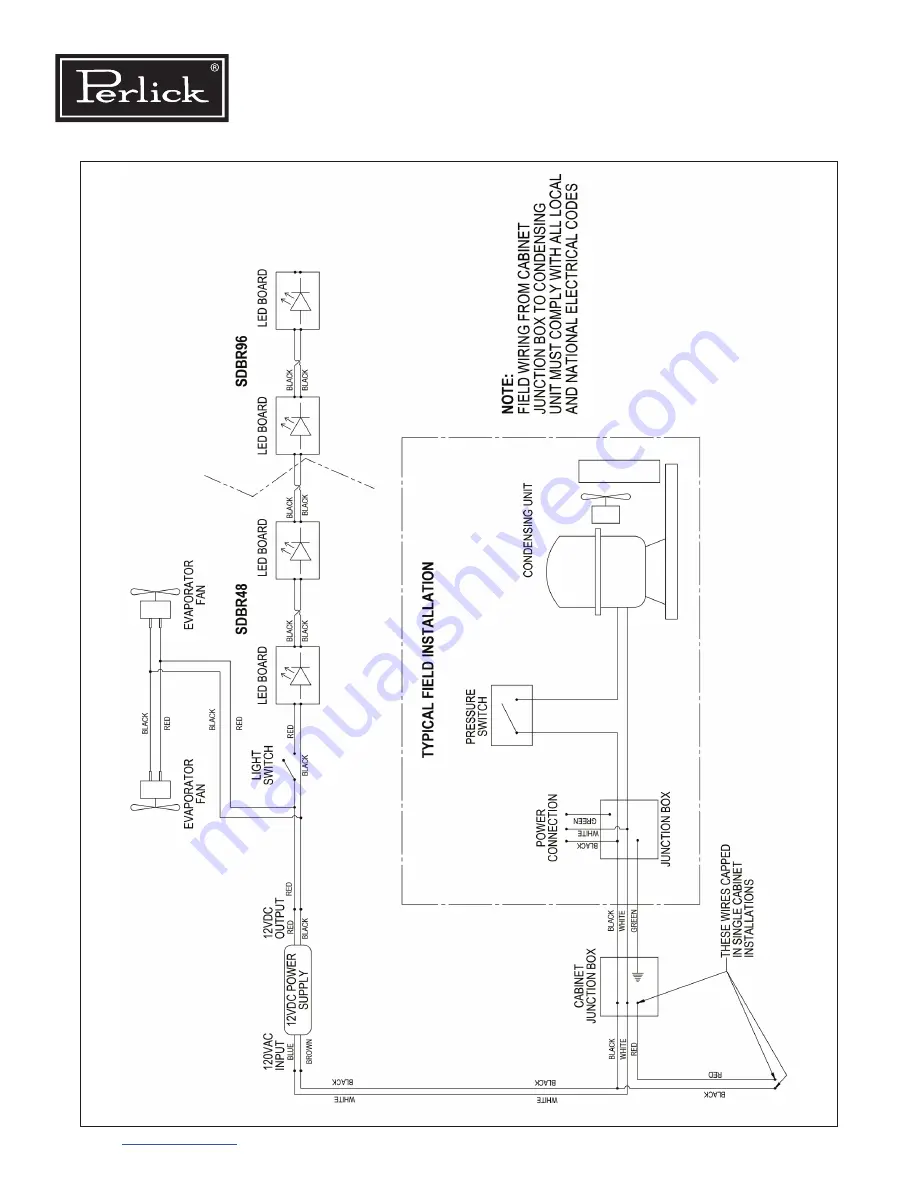
Figure 7-11. SDBR48/SDBR96 Wiring Diagram
SDBR48-SDBR96
57342A-106-120-RevA
Page 1: ...oduct Series Covered in this Manual Self Contained BBS BBSN PTS DZS SDBS SDPS BBSLP DDC DDS Remote BBR BBRN PTR SDBR SDPR BBRLP BBR96 glass door and solid stainless steel door options shown Service Ma...
Page 2: ...porator Coil Self Contained Models 25 6 6 Air Flow Obstructions 25 6 7 Clean Condenser Coil 26 6 8 Ambient Temperature 26 6 9 Compressors and Condensing Unit 27 6 10 Replace Condenser Fan Motor 28 6 1...
Page 3: ...5 2 Drawer Divider Adjustment 58 8 5 3 Cleaning Lubricating Drawer Extenders 58 8 6 Replace Door Drawer Gasket 58 8 7 Replace Door Handle 59 8 8 Locks 59 8 9 Custom Overlay Panels 59 9 0 REPLACEMENT...
Page 4: ...e 7 5 BBSLP Wiring Diagram 36 Figure 7 6 DDS DDC Wiring Diagram 37 Figure 7 7 DZS36 Wiring Diagram 38 Figure 7 8 DZS60 Wiring Diagram 39 Figure 7 9 PTR Wiring Diagram 40 Figure 7 10 PTS Wiring Diagram...
Page 5: ...e 6 1 System Operating Pressures 24 Table 6 2 Compressor Data 27 Table 7 1 Electrical Specifications 31 Table 7 2 Load Operation Modes 46 Table 7 3 Controller Where Used Table 46 Table 7 4 Factory Tem...
Page 6: ...e contact Perlick Customer Service during regular hours of operation 1 2 Model Families This manual contains specific instructions for servicing the Perlick Back Bar commercial refrigeration products...
Page 7: ...ly allowed to be used in refrigerating appliances which are designed for this refrigerant and fulfill the above mentioned standard R290 is heavier than air The concentration will always be highest at...
Page 8: ...Back Bar Operation Installation Manual Return to Table of Contents 8...
Page 9: ...rces of sparking or open flames Ensure the area is free of open flame or burning materials including cigarettes candles or similar materials Do not operate appliances that utilize open flames igniters...
Page 10: ...fault exists that could compromise the refrigerant repair the electrical fault first Before performing service discharge all capacitors in the machine compartment and disconnect electricity to the ap...
Page 11: ...tion openings are critical to the function of the appliance during and after repair Compressors may still contain residual refrigerant in the oil after refrigerant is removed Take these precautions DO...
Page 12: ...the maximum capacity Use appropriate markings and labeling on refrigerant recovery cylinders This includes flammable material symbols and possible additional color markings Storage facilities should c...
Page 13: ...or serious injury if not avoided Indicates hazardous situation that may result in death or serious injury if not avoided Caution indicates hazardous situation that could result in minor or moderate in...
Page 14: ...bent or damaged Straighten fins Control No power to control Refer to Control not functioning Control is not calling for cooling Refer to Control not functioning Probe failure Refer to Table 7 5 for re...
Page 15: ...ng coil is dirty Clean with soft brush and vacuum Incorrect control settings Return to factory settings See Sections 7 5 1 and 7 5 2 Probe failure Refer to Table 7 5 for resistance values Replace prob...
Page 16: ...ront to back and side to side for water to drain properly Sealing compound does not form a complete seal Refer to Section 1 1 Door gasket is damaged Refer to Section 1 1 and 8 6 Remote ONLY Floor drai...
Page 17: ...not operational start relay capacitor Models manufactured after March 2017 Starting device is not operational Models manufactured before March 2017 Replace compressor electrical components Models man...
Page 18: ...7 2 Reconnect wires if needed No power to LED strips 12V Check wiring backwards to light switch Faulty LED strip Replace LED strip Light stays on when door is closed Manual switch is on Turn off manu...
Page 19: ...s repair and recharge See Section 6 13 This is a critically charged system recharging should only be done when all other options have been thoroughly checked Eliwell Control LED Controller display is...
Page 20: ...ation Sealing compound does not form a complete seal Refer to Section 1 1 Door gasket is damaged or out of place Refer to Section 1 1 and 8 6 Condensate drain line air trap is not positioned properly...
Page 21: ...per mounting Refer to Section 8 4 Excessive wear Replace worn parts Refer to Section 8 4 Door handles falling off Improper handle mounting Verify proper mounting Refer to diagram Excessive wear Replac...
Page 22: ...gasket should be pushed in firmly and lay flat Ensure gasket forms a complete seal around door Sealing compound is used to seal wiring and line set pass through between the condenser and the evaporato...
Page 23: ...ation deck can now be pulled straight out Figure 6 5 Pull slowly and carefully to avoid damaging the copper line set The copper line set is coiled with enough additional line to allow condensing unit...
Page 24: ...refrigeration cycle Table 6 1 System Operating Pressures 6 4 4 Service Valves Recording Pressure When installing gauges 1 Initially purge manifold set with refrigerant type used in unit This avoids i...
Page 25: ...ound wire harness and piping Check for other potential sources of air infiltration See Section 6 1 STEP 6 Supply Air Plenum Product Guard Air Intake Reverse steps 1 through 3 to close the evaporator f...
Page 26: ...This results in high head pressures and lower efficiency due to longer run times Use soft brush and vacuum to clean coil every 90 days or more often if conditions require 6 8 Ambient Temperature High...
Page 27: ...1 4 RSCR 6 40 2 74 9 14 BBSN92 1 4 RSCR 6 40 2 74 9 14 PTS36 1 10 RSCR 7 80 7 10 14 90 PTS60 1 5 RSCR 6 72 5 08 11 80 PTS84 1 4 RSCR 6 40 2 74 9 14 DZS36 1 10 RSCR 7 80 7 10 14 90 DZS60 1 5 RSCR 6 72...
Page 28: ...tion 6 2 6 11 Replace Evaporator Fan Motor Self Contained Models Remove grille by removing 3 Phillips head screws one at the top center and two at the bottom edge Cut 2 zip ties holding wire harness...
Page 29: ...eck all brazed connections thoroughly for leaks Look for spots where the sealed system components might have been worn through by structural or cabinet components Check the service ports thoroughly fo...
Page 30: ...egular service System should be kept sealed Do not top off or add refrigerant to an unknown existing charge Completely reclaim existing refrigerant in accordance with EPA regulations and thoroughly ev...
Page 31: ...electrical circuit protection device i e circuit breaker Unit Type Model Number Running Load Amps Electrical Supply Electrical Connection Self Contained BBS36 BBS60 BBS84 BBS108 1 8 2 5 4 2 4 2 120 VA...
Page 32: ...Back Bar Operation Installation Manual Return to Table of Contents 32 7 2 Wiring Diagrams BBR24 BBRN40 57342A 99 120 RevA Figure 7 1 BBR24 BBRN40 Wiring Diagram...
Page 33: ...33 Return to Table of Contents Back Bar Operation Installation Manual BBR48 BBRN60 BBR72 BBRN80 BBR96 57342A 98 120 RevA Figure 7 2 BBR48 BBR72 BBR96 BBRN60 BBRN80 Wiring Diagram...
Page 34: ...BBRLP 95322A 120 RevA Back Bar Operation Installation Manual Return to Table of Contents 34 Figure 7 3 BBRLP48 BBRLP72 BBRLP96 Wiring Diagram...
Page 35: ...WHITE WHITE RED RED RED CONTROLLER SWITCH BBS BBSN 57342C 97 120 35 Return to Table of Contents Back Bar Operation Installation Manual Figure 7 4 BBS36 BBS60 BBS84 BBS108 BBSN32 BBSN52 BBSN72 BBSN92...
Page 36: ...Back Bar Operation Installation Manual Return to Table of Contents 36 Figure 7 5 BBSLP Wiring Diagram SWITCH RED RED RED WHITE RED CONTROLLER WHITE WHITE BBSLP 95321C 120...
Page 37: ...37 Return to Table of Contents Back Bar Operation Installation Manual Figure 7 6 DDS DDC Wiring Diagram WHITE RED WHITE WHITE WHITE RED RED RED CONTROLLER SWITCH DDS DDC 57342C 100 120...
Page 38: ...Back Bar Operation Installation Manual Return to Table of Contents 38 Figure 7 7 DZS36 Wiring Diagram DZS36 57342B 108...
Page 39: ...re 7 8 DZS60 Wiring Diagram WHT NO RED RED SENSING PROBE OUTPUT RED FRONT OF UNIT RED CONNECT TO RED CONNECT TO WHT WHT RED RED FRONT OF UNIT WHT WHT WHT RED COIL CONTROLLER SWITCH RED RED RED WHITE R...
Page 40: ...PTR 57342A 102 120 RevA Back Bar Operation Installation Manual Return to Table of Contents 40 Figure 7 9 PTR Wiring Diagram...
Page 41: ...WHITE RED SWITCH RED WHITE WHITE WHITE RED RED RED CONTROLLER SWITCH PTS 57342C 101 120 41 Return to Table of Contents Back Bar Operation Installation Manual Figure 7 10 PTS Wiring Diagram...
Page 42: ...Back Bar Operation Installation Manual Return to Table of Contents 42 Figure 7 11 SDBR48 SDBR96 Wiring Diagram SDBR48 SDBR96 57342A 106 120 RevA...
Page 43: ...43 Return to Table of Contents Back Bar Operation Installation Manual Figure 7 12 SDBS Wiring Diagram SWITCH RED RED WHITE RED WHITE CONTROLLER WHITE WHITE SDBS 57342C 105 120...
Page 44: ...SDPR 57342A 104 120 RevA Back Bar Operation Installation Manual Return to Table of Contents 44 Figure 7 13 SDPR Wiring Diagram...
Page 45: ...WHITE CONTROLLER RED SWITCH RED WHITE WHITE WHITE RED RED SWITCH SDPS 57342C 103 120 45 Return to Table of Contents Back Bar Operation Installation Manual Figure 7 14 SDPS Wiring Diagram...
Page 46: ...xell Controller To view set point press and release SET key Refer to Table 7 4 for factory set point To change set point value press and hold SET key for at least 2 seconds The set point value will be...
Page 47: ...ne of the preset applications when exiting stand by mode is Set the instrument in stand by mode by pressing the button for time H02 Exit stand by mode by pressing the button for time H02 Within 10 sec...
Page 48: ...head screws one at the top center and two at the bottom edge Remove 2 screws holding control cradle to unit Remove clips holding the controller to the cradle Control cradle will slide freely from the...
Page 49: ...n wiring harness Disconnect DC driver leads from the main wiring harness Remove main wiring harness by disconnecting Molex connector from molded receptacle Remove green probe connector from controller...
Page 50: ...rew Use pliers if needed to secure probe notch to sheet metal probe bracket See Figure 7 2 Crimp gently to avoid damaging the probe The notch in the probe body should fit into the bracket slot to enca...
Page 51: ...Strip ELECTROCUTION HAZARD Never attempt to repair or perform maintenance on unit until main electrical power to the unit has been disconnected Open door or remove upper drawer See Figure 8 13 Using...
Page 52: ...ior LED Light 7 7 Replace DC Driver Inverter Locate DC Driver Inverter on ceiling of refrigeration compartment Check voltage If not within range printed on the part replace the part Disconnect DC driv...
Page 53: ...sure the unit is level Ensure doors and drawers are sealing properly when closed No door adjustments should be necessary unless there is major structural damage to cabinet 8 2 Reverse Door Swing Note...
Page 54: ...val Remove hole plugs from top and bottom hinge bracket mounting holes See Figure 8 2 Place plugs in holes on opposite side made vacant by removing hinges in step 3 Using screws removed in step 3 inst...
Page 55: ...8 5 Rotate front panel 180 top to bottom Reattach using same screw and mounting holes Figure 8 5 Removing Front Panel Insert bearing into door top hinge bracket See Figure 8 6 Insert V block into door...
Page 56: ...Insert and tighten lower hinge pin to complete assembly 8 3 Replace Door Hinge See Section 8 2 for hinge replacement instructions 8 4 Sliding Door Models 8 4 1 Removing Installing Sliding Doors To rem...
Page 57: ...e detents Reinstall screw Detent farthest from left provides the least amount of tension Units are shipped from factory with springs set at the weakest setting 8 4 3 Torpedo Spring Adjustment Remove d...
Page 58: ...ion Locate the latch in the middle of both extenders Push each latch forward and lift front of latch up unlocked position then lift the front of the drawer and pull out Place drawer on to the extender...
Page 59: ...andle can now be removed 4 X 3 8 hex head bolts Reverse these steps to replace door hinges overlay panel and gasket 8 8 Locks Gain access to back side of the lock by following directions to remove doo...
Page 60: ...Back Bar Operation Installation Manual Return to Table of Contents 60 9 0 Replacement Parts For parts ordering call 844 411 8050 9 1 Refrigeration Module BBS BBSN PTS SDBS SDPS DDS DDC Model Series...
Page 61: ...Assembly 1 1 12 Probe Temperature 1 1 1 13 Sleeve Sensor Insulating 1 1 1 14 Tube Drain Evaporator Pan to Condenser Pan 1 1 1 15 Bracket Temperature Sensor 1 1 1 16 Bracket Top Pull Down 2 2 2 17 Sta...
Page 62: ...Back Bar Operation Installation Manual Return to Table of Contents 62 9 2 Refrigeration Module BBSLP Model Series...
Page 63: ...1 11 Low Side Foamed Assembly 1 1 12 Probe Temperature 1 1 1 13 Sleeve Sensor Insulating 1 1 1 14 Tube Drain Evaporator Pan to Condenser Pan 1 1 1 15 Bracket Temperature Sensor 1 1 1 16 Bracket Top Pu...
Page 64: ...of Contents 64 BBSLP MODELS ITEM NUMBER DESCRIPTION 1 DOOR QTY 2 DOOR QTY 3 4 DOOR QTY 34 Bracket Ratcheting Strain Relief 1 1 1 35 Strain Relief 1 1 1 36 Harness Fan Motors Low height 1 37 Harness 12...
Page 65: ...65 Return to Table of Contents Back Bar Operation Installation Manual 9 3 Refrigeration Module DZS Model Series...
Page 66: ...Temperature 1 1 1 13 Sleeve Sensor Insulating 1 1 1 14 Tube Drain Evaporator Pan to Condenser Pan 1 1 1 15 Bracket Temperature Sensor 1 1 1 16 Bracket Top Pull Down 2 2 2 17 Standoff Grille 1 1 1 18 L...
Page 67: ...LS ITEM NUMBER DESCRIPTION QTY 2 DOOR QTY 3 4 DOOR QTY 35 Strain Relief 1 1 1 36 Nylon Standoff 4 4 4 37 Controller Board Damper Dual Zone 1 1 1 38 Screw Sheet metal 6 x 1 2 a 2 2 2 39 Relay Pump 1 1...
Page 68: ...Back Bar Operation Installation Manual Return to Table of Contents 68 9 4 Refrigeration Module DDS IR Model Series...
Page 69: ...3 Sleeve Sensor Insulating 1 1 14 Tube Drain Evaporator Pan to Condenser Pan 1 1 15 Bracket Temperature Sensor 1 1 16 Bracket Top Pull Down 2 2 17 Standoff Grille 1 1 18 LED Driver 1 1 19 Controller 1...
Page 70: ...9 5 Fan Motor Assembly Parts Self Contained Model Series SELF CONTAINED MODELS ITEM NUMBER DESCRIPTION QTY 01 Motor Fan 1 02 Panel Fan Mounting 1 03 Panel Inner Grille 1 04 Screw Motor Mounting 4 05...
Page 71: ...anual 9 6 Low Profile Evaporator Parts BBSLP Model Series LOW PROFILE MODELS ITEM NUMBER DESCRIPTION QTY 01 Fan Evaporator 3 02 Panel Fan Mounting 1 03 Screw Fan Mounting 12 04 Grille 1 05 Screw Grill...
Page 72: ...tents 72 9 7 Remote Evaporator Parts BBR BBRN PTR SDBR BBRLP Model Series REMOTE MODELS ITEM NUMBER DESCRIPTION QTY 01 Motor Fan 1 02 Panel Fan Mounting 1 01 Bracket Fan 2 02 Control Temperature 1 03...
Page 73: ...REMOTE MODELS ITEM NUMBER DESCRIPTION QTY 06 Fan Panel Evaporator Right 1 07 Fan Panel Evaporator Left 1 08 Plug Dome 1 09 Motor Fan 2 10 Blade Fan 2 11 Evaporator Assembly 1 Coil 21 Fin 1 Tube Evapor...
Page 74: ...Back Bar Operation Installation Manual Return to Table of Contents 74 NOTES...
Page 75: ...75 Return to Table of Contents Back Bar Operation Installation Manual NOTES...
Page 76: ...8300 West Good Hope Road Milwaukee WI 53223 Toll Free 800 558 5592 Fax 414 353 7069 www perlick com...