2
019-
02
10
Functional Safety M-LB-(Ex-)2000-System
Planning
3.2
Assumptions
The following assumptions have been made during the FMEDA:
•
The device will be used under average industrial ambient conditions comparable
to the classification "stationary mounted" according to MIL-HDBK-217F.
Alternatively, operating stress conditions typical of an industrial field environment
similar to IEC/EN 60654-1 Class C with an average temperature over a long period
of time of 40
º
C may be assumed. For a higher average temperature of 60
º
C,
the failure rates must be multiplied by a factor of 2.5 based on experience.
A similar factor must be used if frequent temperature fluctuations are expected.
•
The control loop is considered to be either isolated from ground (except i. e. components
within the protection module), or one of the protected lines is directly connected to ground.
In both cases, a failure mode leads to a safe reaction or has no effect, so the worst case
is assumed to be a no effect failure.
•
Failure rate based on the Siemens standard SN 29500.
•
Failure rates are constant, wear is not considered.
•
The control loop has a hardware fault tolerance of
0
and it is a type
A
device.
A SFF value for this device is not given, since this value has to be calculated in conjunction
with the connected field device, as described in the following section.
•
The devices M-LB-(Ex-)2114(.SP) do not withstand conducted RF immunity tests
(10 V according to IEC/EN 61000-4-6).
The devices M-LB-(Ex-)2114(.SP) and M-LB-(Ex-)2144(.SP) do not withstand immunity
tests against conducted common mode disturbances at spot frequencies
(100 V according to IEC/EN 61000-4-16).
Cause is that the limit values of the protective elements for the application
are lower than the test limits required by the standards. The user has to decide whether
the devices are suitable for the application or whether the devices with higher voltage limits
must be used.
Application
The surge protection barrier and the connected device (transmitter, isolator or actuator)
have to be considered in combination. The PFD
avg
/PFH budget of the device categories
in the entire safety loop is:
•
Actuator (valve) 40 %
•
Transmitter (sensor) 25 %
•
Isolator 10 %
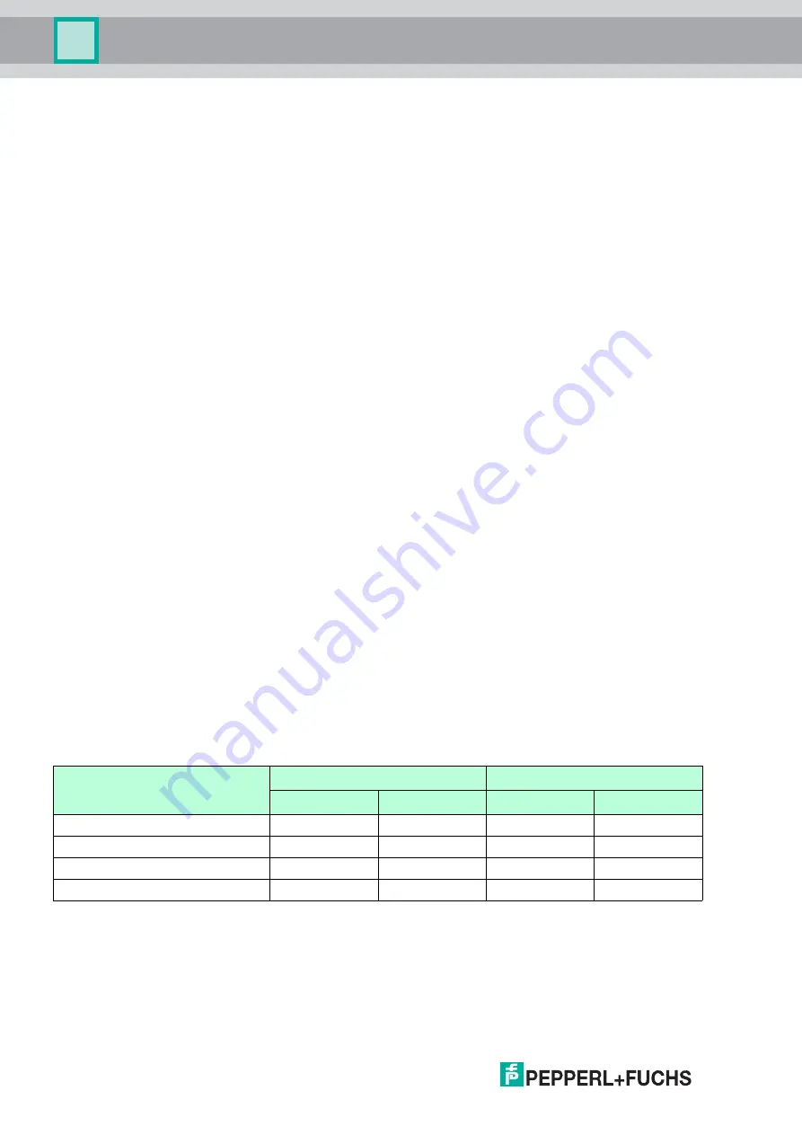
As an overview for the SIL2 or SIL3 safety loop this means:
Device category
SIL2
SIL3
PFH
PFD
avg
PFH
PFD
avg
Total
10
-6
10
-2
10
-7
10
-3
Actuator (40 %)
4 x 10
-7
4 x 10
-3
4 x 10
-8
4 x 10
-4
Transmitter (25 %)
2.5 x 10
-7
2.5 x 10
-3
2.5 x 10
-8
2.5 x 10
-4
Isolator (10 %)
10
-7
10
-3
10
-8
10
-4
Table 3.1
Overview PFD
avg
/PFH budget


