


2
0
2
0
-0
6
12
Product Description
2.3
Interfaces and Connections
The contact arrangements below show the front view of the plug-in area of the connectors.
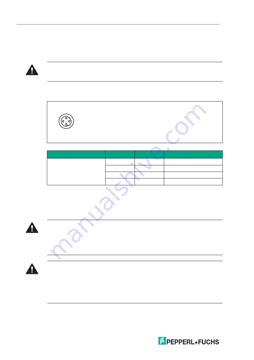
Fieldbus Connection X01, X02
•
Connection: M12 socket, 4 pin, D-coded
•
Color coding: green
Figure 2.2
Schematic drawing of port X01, X02
Connection for IO-Link, digital inputs/outputs X1 - X8
•
Connection: M12 socket, 5 pin, A-coded
•
Color coding: black
Caution!
Risk of destruction!
Never route the power supply to the data cable.
Port
Pin
Signal
Function
Ports X01, X02
1
TD+
Transmit data +
2
RD+
Receive data +
3
TD-
Transmit data -
4
RD-
Receive Data -
Table 2.4
Assignment of port X01, X02
1
3
2
4
Caution!
Risk of destruction with external sensor supply!
The module infeed for the sensor supply U
S
may only be provided over the specified power
connection (Power X03/X04 >> U
S
+24 V/GND_U
S
) for the module. It is not permitted to supply
external power via the IO-Port (port X1 - X8 >> pin 1/pin 3) and this may destroy the module
electronics through power feedback.
Caution!
Do not compromise galvanic isolation through incorrect cabling!
The sensor supply (port X5 - X8 >> pin 1/pin 3) and extended sensor supply (port X5 - X8 >>
pin 2/pin 5) are galvanically isolated from each other. If the reference potentials (GND_
US
–
pin
3) and (GND_U
Aux
–
pin 5) are connected, excessive equalization currents may flow. In this
case, it is not permitted for a sensor to be connected to (port X5 - X8 >> pin 2)!
Eliminating the galvanic isolation is not recommended.


