


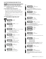
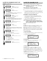

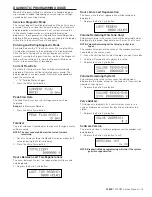


MASTER PROGRAMMING MODE FLOW
CHART
continued
Options:
Valve Address #1 (First Control Valve)
Valve Address #2 (Second Control Valve)
(Default)
Valve Address #3 (Third Control Valve)
Valve Address #4 (Fourth Control Valve)
Options:
System 4 (single unit)
System 5 (2-4 units)
System 6 (2-4 units)
System 7 (2 units)
System 9 (2-4 units)
Example:
System Type 4, Single Unit
Example:
Valve Address #2 (Second Control Valve)
(Default)
Options:
2 Valves in the System
(Default)
3 Valves in the System
4 Valves in the System
Example:
2 Valves in the System
(Default)
Options:
Time Clock Delayed (System 4 Only)
(Default)
Meter Immediate (All System Types)
Meter Delayed Fixed Reserve (Systems 4 & 6 Only)
Example:
Time Clock Delayed
(Default)
Example:
00%
(Default)
Options:
English
Spanish
Example:
English
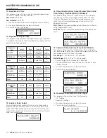
Options:
Downflow
(Default)
Downflow Fill First
Filter
Iron Filter
(Do Not Use)
Example:
Downflow
(Default)
Options:
00:06:00
(Default)
Range:
1 second to 99 minutes (1 hour, 39 minutes)
Example:
00:06:00
(Default)
(Hours:Minutes:Seconds)
Range:
2 to 4 Valves in the System
NOTE: This screen will not display for System Type 4.
NOTE: This screen will not display for System Type 4.
Example:
U.S. Gallons
(Default)
Options:
U.S. - Gallons
(Default)
European Units - Liters (Metric)
NOTE: In European Units - Liters (Metric) mode, the display will be in
24-hour time.
NOTE: In U.S. - Gallons mode, the display will be in 12-hour time.
Options:
Grains (in U.S. Format)
(Default)
Grams (in Metric Format)
Example:
Grains
(Default)
Range:
9,000 to 9,900,000 Grain Capacity in U.S. Format
90.0 to 190,000 grams CaCO
3
Capacity in Metric Format
Range:
0 to 50%
NOTE: Use the Shift button to move to the left.
Range:
1 to 199 Grains/Gallon (U.S. Format)
2 to 199 miligrams CaCO
s
/L (Metric Format)
Example:
15 GPG (U.S. Format)
(Default)
NOTE: Use the Shift button to move to the left.
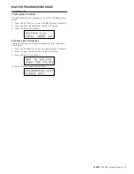
NOTE: This screen will only display on the lead unit for System Types 6 & 7.
For all other System Types, it will display for all units.
Example:
Off
(Default)
Options:
Off
(Default)
or On
Example:
1 Day
Range:
1 to 99 Days
Example:
2:00 A.M.
(Default)
Options:
A.M. (U.S. Format)
HR (Metric Format)
NOTE: Regeneration time will not appear unless Regeneration Day Override
is on.
Example:
Cycle 1 in Back Wash Mode
Options:
Regeneration Cycle Step #1
Regeneration Cycle Step #2
Regeneration Cycle Step #3
Regeneration Cycle Step #4
Regeneration Cycle Step #5
Regeneration Cycle Step #6
NOTE: Please refer to the “Regenerant Flow Default Cycle Steps & Times”
in the Master Programming Mode section of the manual.
NOTE: If Stager is chosen for Valve Type, the Regeneration Cycle Step
description will not display.
Example:
Auxiliary Relay is Disabled
Options:
Enabled
Disabled
(Default)
Example:
Auxiliary Relay Output in Start 1 at
0 hours, 0 minutes, & 0 seconds
Range:
00:00:00 to 18:00:00
NOTE: Only displayed if Auxiliary Relay is enabled in previous screen.
Auxiliary Relay will only display if Chemical Pump is OFF for System
Types 6 & 7.
Example:
Auxiliary Relay Output in End 1 at
0 hours, 0 minutes, & 0 seconds
Range:
00:00:00 to 18:00:00
Example:
Chemical Pump is Disabled
Options:
Enabled
Disabled
(Default)
NOTE: This screen will only display on the lead unit for System Types 6 & 7.
For all other System Types, it will display for all units.
Example:
Chemical Pump Auxiliary Relay
Volume at 0 Gallons
Range:
000 to 999 gallons in U.S. Format
0.000 to 9.999 L in Metric Format
NOTE: Only displayed on units that physically have a meter (Lead always has
a meter). Only shown if Auxiliary Relay is disabled on System Types 6 & 7.
Example:
Chemical Pump Auxiliary Relay at 0 Hours,
0 Minutes, & 0 Seconds
Range:
00:00:00 to 02:00:00
Example:
1.2 Turbine Flow Meter
Options:
1.2 Turbine
Generic
NOTES: Default flow meter type is based on the valve type. This screen will
only display on the lead unit for System Types 6 & 7. All other system types
it will display for all units.
Example:
Maximum Flow Rate of 0 gpm
Range:
20 - 2,000 gpm (U.S. Format)
2.0 - 200.0 L (Metric Format)
NOTE: Only displayed if “Generic” is chosen for the flow meter.
Range:
1 - 99 Gallons (U.S. Format)
0.1 - 09.9 L (Metric Format)
Pulses: 1 - 99
Options:
Gallons (U.S. Format)
Liters (Metric Format)
Example:
Add 1 Gallon for Each Pulse in U.S. Format
NOTE: Only displayed if “Generic” is chosen for the flow meter.
Example:
Master Programming Mode is Exiting
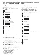
MASTER PROGRAMMING GUIDE
When the Master Programming Mode is entered, parameters
can be set to make the timer(s) function as needed.
NOTE: Depending on current option settings, some displays
cannot be viewed or set.
Entering Master Programming Mode:
1. Press and hold the Shift and Up buttons for 5 seconds.
OR
2. Set the time of day display to 12:01 PM or 12:01HR (See the
“Setting the Time of Day” section on the “Timer Operation”
page). Then go to the main display screen, press the Up and
Down buttons at the same time for 5 seconds.
Exiting Master Programming Mode
1. Press the Extra Cycle button once per display until all
are viewed. Master Programming Mode is exited and the
normal display screen appears.
2. To exit the Master Programming Mode without saving
changes, press the Diagnostic button.
NOTE: If no keypad activity is made for 5 minutes while in
the Master Programming Mode, or if there is a power
failure, no changes will be saved, and the unit will go
back to the main display screen.
Resets
Soft Reset:
Press and hold the Up and Down buttons for 25
seconds until 12:00PM (or 12:00HR) appears. This resets all
parameters except for the flow meter totalizer volume.
Master Reset:
Hold the Extra Cycle button while powering up
the unit. This resets all of the parameters in the unit. Check
and verify the choices selected in Master Programming Mode
prior to this procedure.
1. Choice of Language
This option selects the language for programming and display.
1. Use Up or Down to select language.
2. Press the Extra Cycle button.
2. System Type
This program type selects the system type (4, 5, 6, 7, or 9).
1. Use Up or Down buttons to adjust this value.
2. Press the Extra Cycle button.
3. Valve Address
This program step selects the valve address (1, 2, 3, or 4)
within the network. The address is needed for each timer
for communication. The #1 is the “master” or “lead” which
contains programmed parameters, that will be used by all of
the timer(s) in the network to control Regeneration, in Service,
or Standby of all the valve(s) in the system. This option will be
skipped if System 4 is selected.
1. Use Up or Down buttons to adjust this value.
2. Press the Extra Cycle button.
10 •
FLECK
7000 NXT Service Manual


