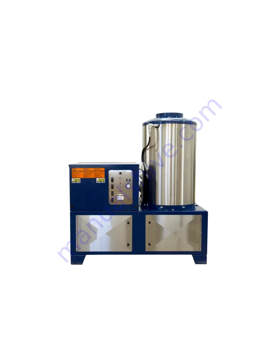
PEM P-300
SprayW
and™
Pretreatment Application System
Installation
•
Operation
Maintenance
Troubleshooting
Revision 11.16.15
Page 1: ...PEM P 300 SprayWand Pretreatment Application System Installation Operation Maintenance Troubleshooting Revision 11 16 15 ...
Page 2: ......
Page 3: ...essure 12 Guide to gas line pipe size 13 Venting the machine to the outside 14 Water supply 15 Coil conditioner 15 Neutralizer 16 Wand and Hose 16 Initial start up 17 Control panel 17 Switches 17 Pump switch 17 Burner switch 17 Indicator lights 17 Pump motor overload indicator light 17 Flow indictor light 17 Temp indicator light 17 Fuel indicator light 17 Temperature control 18 Initial startup pro...
Page 4: ...1 Servicing the ceramic plungers and V packings 32 Removing the pump manifold head 32 Replacing plungers 33 Replacing V packings 34 Reinstalling the manifold head 34 Intermittent ignition device 38 Wiring 38 Engineering data 39 Gas Valve 40 Adjusting the pilot light 41 Troubleshooting 42 Gas burner malfunction 43 Intermittent ignition device problems 44 Pump malfunction and pressure delivery probl...
Page 5: ...le Another option delivers sealer right from the drum through a low volume low pressure pump Warning To prevent injury and equipment damage thoroughly read and understand the contents of this manual before operating the P 300 General specifications Model P300 HP 7 5 Electrical 230 V 3 phase 20 A 460 V 3 phase 10 A Connection 4 wire through junction box GPM 5 Pressure Phosphatize 1500 PSI Optional ...
Page 6: ...tended to two full years or 2000 hours whichever occurs first Three 3 Years Parts Belt guards Frame Float tank Pump drive assembly Float tank Coil wrapper Heating coils Self contained and stationary models Two 2 Years Parts Plumbing One 1 Year Parts Control switches Electric motors Float valves Safety switches Pulleys Thermostat Ground fault circuit interrupter Ninety 90 Days Parts Lights Trigger ...
Page 7: ...ation charges in connection with the replacement or repair of the defective parts PEM Corporation makes no warranty with the respect to trade accessories They are subject to the warranties of their manufacturers Any implied or statutory warranties including any warranty of merchantability or fitness for a particular purpose are expressly limited to the duration of this written warranty We make no ...
Page 8: ...rself that it is safe for you and for other persons You must also ensure that the product will not be damaged or made unsafe by the procedure that you use Warning Fluids under pressure spray can be nearly invisible and can penetrate the skin and cause extremely serious injury Avoid contact with high pressure spray Specifically Never point the spray gun at any part of your body or at any other pers...
Page 9: ...eave an operating machine unattended Always shut off the machine and relieve pressure before leaving the machine Never spray inflammable or toxic liquids or chemicals such as insecticides or weed killer Never operate the machine when combustible fumes or dust may be present Never use detergents that are not compatible with the discharge hose Read and follow instructions provided by the detergent m...
Page 10: ...otection and rubber gloves when handling or using chemicals Always have a clean supply of water available to wash off any contact with the skin or eyes Should any chemical contact the eyes immediately flood the eyes with clean water and seek medical attention at once If skin contact occurs flood the affected area with plenty of water for 15 minutes If irritation persists seek medical attention If ...
Page 11: ...ch operations If leaking is evident do not use the hose Contact a qualified pressure washer service representative Never leave the discharge hose lying on the floor or ground to be driven over by vehicles or damaged by falling objects Always coil and hang the hose immediately after use Danger To prevent unexpected energizing startup or release of energy that could cause injury to people working on...
Page 12: ...formation from this plate in Table 1 Figure 1 Identification plate location on the back of the machine Model___________________________________ Output________ Gpm_________ Psi__________ Fuel_____________________________________ Elec _______Ph______ Volts_____ Amps_______ Serial Number_____________________________ Table 1 Machine identification from the plate Machine location The gas fired pressure...
Page 13: ...ine setup Exact machine setup may vary somewhat between machine models however the following information will be a general guideline Contact your dealer or authorized service representative for special installation or setup requirements Note In order to avoid unnecessary expense of complying with or correcting the violation of a regulation investigate all applicable state and local codes before at...
Page 14: ... by a licensed electrician and must conform to all federal state and local codes and ordnances regarding three phase electrical requirements Mechanical gas service Have a HVAC expert set up gas connections Burner fuel pressure Adjust the pressure to the type of burner fuel as follows Natural gas fired machines Operate on 3 of water column 2 oz pressure at the valve and must have from 5 to 9 water ...
Page 15: ...ll a gas shutoff valve in back of the machine on the gas line with a union between the valve and the gas regulator see Figure 4 Prior to operating the burner system purge the new lines If this is not done starting the burner can be difficult Figure 4 Gas Valve Guide to gas line pipe size See Table 2 for the minimum gas line iron pipe size required for gas supply per length of gas line from the val...
Page 16: ... is not in use Install UL listed weather cap on top of the building If the machine is used in an enclosed area and you are putting a chimney on it be sure a draft diverter available as an option see Figure 4 is installed and the chimney is as at least the same size as the stack on the machine 12 inches Poor draft will cause the unit to soot and not operate efficiently Position the machine to ensur...
Page 17: ...in the back of the machine Caution To prevent machine damage use only perfectly clean water If the water supply exceeds 6 grains of hardness 100 ppm the coil conditioner will extend the coil life and maintain machine efficiency Coil conditioner The chemical supplier sets the coil conditioner flow rate by adjusting the conditioner pump see Figure 7 located under the top cover Coil conditioner is pu...
Page 18: ...chemical injector is sensitive to pressure If the nozzles are damaged or are the wrong size the injector may not work If the hose is damaged or kinked e g ran over by a forklift it may also cause the injector to malfunction Non standard piping or the addition of valves and elbows may also cause injection problems Black wand will be used for Rinse ONLY Do not use the black wands for chemical applic...
Page 19: ...dicator light turns on turn off the pump switch and let the machine cool down Turn the pump switch on again If the pump motor continues to shut down call P E M Flow indictor light This light will glow red during normal operation when the gun trigger is pulled indicating the circuit through the flow switch is good It will turn out when the gun trigger is released If the light remains out when the t...
Page 20: ... water temperature Caution Left loose the gun or wand assembly could damage and cause injury to personal or property damage Do not start the machine without having the trigger gun or wand completely under your control Caution Never run the cleaning unit dry Costly damage to the pump will result Always be sure the water supply is completely turned on before operating the machine Figure 9 Control pa...
Page 21: ... the burner switch off and back on Continue to do this until the temp light illuminates This indicates the pilot valve solenoid is open and the igniter switch activated the pilot light The Temp light will come on The system is ready to fire Note The system has series of safety checks that must be satisfied before the Temp light comes on If the Temp light is not on the burner will not fire If the T...
Page 22: ...ted using the color coded metering orifices that can be threaded into the chemical pick up An assortment of various sized metering orifices is included with the machine in the instruction packet See Table 3 The injector will draw approximately 2 5 chemical with no metering tips The metering tips can be used to reduce this percentage in 0 2 increments down to approximately 0 8 percent These meterin...
Page 23: ...s If chemical does not come up check the chemical filter on the end of the chemical hose Caution Chemicals not compatible with the system materials will cause damage to the components down the line from the chemical injector Ensure the chemicals will not damage stainless steel Burna N and Viton Warning High pressure spray detergents fluid injector or debris dislodged by the high pressure spray can...
Page 24: ...e machine Caution Never adjust or modify the unloader valve which is located next to the pump and is used to bypass the coil when the wand is not in use Adjusting the unloader valve will not increase performance of the unit and will void the manufacturer s warranty Caution Do not drag the hose over an abrasive surface such as cement This will cause excessive wear and shorter hose life Lift the hos...
Page 25: ...he float tank and refill it with the antifreeze solution 4 Hold open the trigger gun while keeping the float tank full of the antifreeze solution 5 Turn the Pump switch on When antifreeze solution appears at the end of the gun release the trigger once or twice and then turn the Pump switch off 6 When preparing to operate the machine the next time have an antifreeze container handy Reconnect the wa...
Page 26: ...prevent accidental startup Pressure hose Inspect the hose for wear or damage see Figure 10 If there is damage replace the hose Do NOT repair it Wrap up the hose as soon as you turn off the machine and store it on the hose hooks or other safe location Caution Avoid extending the hose across high traffic areas which can damage the hose Never leave the hose where it can be run over by any type of veh...
Page 27: ... red dot in the middle the oil level should be at the red dot If the oil is low remove the fill plug and add oil 2 Fill the crankcase to the red dot on the site glass with SAE 30 weight oil preferably with no detergent Do not overfill 3 Replace the fill plug Change the oil after the initial 50 hours of operation and then after every three months or 500 hours of operation whichever occurs first Cha...
Page 28: ...e that 100 to 110 lbs is registered on the spring scale when the pump is secured in the operating position 3 To adjust the belt tension loosen the four pump main frame attaching bolt nuts one half to one turn Turn the tension bolt nut clockwise to tighten the belt or counterclockwise to loosen it 4 Tighten the mount bolt nuts 5 Using a straight edge verify the pump drive pulley alignment If it is ...
Page 29: ... 10 50 and 100 Pressure rating 316 stainless steel 6000 psig CWP Brass 3000 psig Temperature rating Vitron 15 F to 400 F Buna N 30 F to 4275 F Ethylene propylene rubber 70 F to 275 F This filter traps any mineral chips or scale in that breaks loose from the I D of the coil If this debris is not filtered it could plug the orifices in the chemical injector Service this filter weekly as follows 1 Rem...
Page 30: ...eteriorate Formations can break loose and clog some of the washer components The deposits also restrict flow through the coil and may eventually completely plug it see figure 15 Figure 15 Coil deposits The symptoms of a scaled coil are slow heating inadequate heat rise loss of nozzle pressure and a continuous motor overload In areas with hard water plugging can occur in less than a month unless th...
Page 31: ...he descaler for 5 minutes Restart the descaler and run for 10 minutes 6 Repeat step 5 until the discharge chemical is no longer frothy when the chemical exits like it entered This indicates the chemical no longer has minerals to react with 7 Stop the descaler Carefully lift the pick up hose out of the descaling compound Start the descaler and run for 10 seconds to generator a second air slug Place...
Page 32: ...ne with a mild detergent Danger Do not clean or wash the machine using its own spray gun The machine is water protected but not water proof Cleaning the machine in this matter will increase the risk of serious or fatal electrical shock and damage to the machine ...
Page 33: ...anufacturer Two kits will be needed to repair all the valves in the pump The kit includes new O rings and a valve assemblies valve seat poppet spring and retainer all preassembled Service the valves using the kit as follows 1 Remove each valve plug using a 24 mm socket see Figure 16 Figure 16 Removing valve plugs 2 Examine the O ring gaskets and replace if needed see Figure 17 Figure 17 Examining ...
Page 34: ...avity 5 Install the new O ring in the valve cavity 6 Insert the new valve assembly into the valve cavity 7 Replace the valve cap and torque it to 70 75 foot pounds Servicing the ceramic plungers and V packings Removing the pump manifold head 1 Using a 6 mm hex key wrench remove the eight cap bolts from the manifold head see Figure 19 Figure 19 Removing the cap bolts ...
Page 35: ...se be careful not to damage the plungers 3 The V packing assemblies may come off with the head If not slide them off and examine the ceramic plungers Their surface should be smooth and not scored or pitted Clean them if necessary and replace them if they are damaged as follows Replacing plungers 1 Using a 10 mm socket remove the ceramic plunger and plunger retainer from the piston rod see Figure 2...
Page 36: ...ont male adapter and the V packing 4 Examine the adapters and v packing for wear and replace as needed Examine the seal case O ring 5 Install the new head ring 6 Coat the front V packing with a thin film of grease and insert it in the cavity Repeat with the second V packing Lubricate the seal case O ring 7 Firmly press the seal cases into the V packing 8 Press the low pressure seal into the seal c...
Page 37: ...35 P a g e Figure 22 Manifold head torque sequence Figure 23 Pump exploded view ...
Page 38: ...G1 5150G1 1 30 48224 AL Cover Bearing Blind 1 32 46798 Cap Oil Filler Domed 1 33 14179 NBR O Ring Bubble 2 Gasket 80 D 1 37 92241 Gauge Oil Bubble w Gasket 80 D 1 38 44428 NBR Gasket Flat Oil Gauge 80 D 1 40 92519 STZP Screw Sems M6x16 4 48 25625 STCP Plug Draign 1 4 x 19BSP 1 49 23170 NBR O Ring Drain Plug 70D 1 50 46940 AL Cover Rear 1 51 14044 NBR O Ring Rear Cover 1 53 48617 AL Crankcase 1 64 ...
Page 39: ...ng 6 128 46618 NY Adapter Male 3 139 22179 BBCP Plug Inlet 1 2 NPT 1 162 Back up Ring Seat 6 163 17457 NBR O Ring Seat 6 11685 FPM O Ring Seat 6 164 46658 S Seat 6 166 46429 S Valve 6 167 43750 S Spring 6 168 44565 PVDF Retainer Spring 6 172 17549 NBR O Ring Valve Plug 6 26996 FPM O Ring Valve Plug 6 173 48365 D Baku up Ring Valve Plug 6 174 45900 BB Plug Valve 6 185 46886 FBB Manifold Head 1 188 ...
Page 40: ...connections to the control module Refer to Figure 24 for proper hookup See the front of the device Figure 25 for a key to the fail codes which are indicated by a green LED located next to the cable connector Refer to the troubleshooting section for Troubleshooting procedures Warning To prevent shock and damage to equipment do not apply power to the control module until wiring is completed and the ...
Page 41: ...ame failure response time Main gas shut off 2 0 seconds max Pilot gas Continuous Flame failure re ignition time 0 8 seconds max Voltage 24 Vac 60 Hz or 120 Vac 60 Hz Fuse input current drain 0 05 Amp 120 Vac control module only Note Total current drain for control will include gas valve loads in addition to control module current drain Operating temperature range 0 to 175 F Spark voltage 25kV Peak...
Page 42: ...installer is a qualified serviceperson Shut off the gas supply before starting installation or service Do not connect the appliance before pressure testing To prevent damage to the thermostat do not short the gas valve terminals Do not grip control the body with a wrench or vise Use the inlet boss only Leak test after installation or service With gas flowing through the control main burner on coat...
Page 43: ...g the pilot light 1 Remove the adjusting cap using a fine screwdriver 2 The pilot flame should be about 1 inch high Turn the pilot adjustment cap screw clockwise to make the pilot lower Turn the pilot adjustment cap counterclockwise to make the pilot higher ...
Page 44: ...vice of the machine It does not give all the possible methods to correct the problems listed but is meant to stimulate a train of thought and indicate a work procedures directed toward finding the source of the problem Most problems are simple and easily corrected To save time and trouble always check the easiest and obvious thing first Study the problem thoroughly and ask yourself these questions...
Page 45: ...djustment 1 Install a draft diverter see the Installation section or relocate the machine to a less drafty area or provide shields or walls to isolate the burner 2 Replace electrode 3 Install a larger gas supply hose 4 Adjust the flame to reasonable size 5 Fix intermittent ignition as follows a Repair b Replace c Adjust Burner will not light 1 No fuel 2 Pilot out 3 Thermostat set too low 4 Faulty ...
Page 46: ...ction and pressure delivery problems Problem Probable cause Solution Low pressure 1 Worn or oversize spray nozzle 2 Clogged water inlet strainer 3 Out of detergent pump sucking air through detergent line 4 Air leak in inlet plumbing 5 Belt slipping 6 Dirt or foreign particles in the valve assembly 7 Worn or damaged inlet or discharge valve 8 Inline filter plugged 9 Coil scale 10 Faulty unloader 1 ...
Page 47: ... adequate tap water supply 2 Check key and tighten set screw 3 Replace bearing s 4 Replace pump Oil leaks Worn crank seals crankcase cover and seal or drain plug Replace seals Excessive pump shaft play Worn and loose bearings Replace bearings Check bearing seals spacers and retainers replacing any worn parts Irregular spray pattern Worn or partly clogged spray nozzle Clean or replace nozzle ...
Page 48: ...n valve in the pump Remove and replace pump valve see the Repair section Chemical system malfunction Problem Probable cause Solution Injector s won t draw 1 Plugged wand nozzle 2 Damaged wand nozzle 3 Chemical pick up filter clogged 4 Injector clogged 5 Hose damaged 6 Not adequate flow pressure 7 Temperature too high 1 Clean or replace nozzle 2 Replace nozzle 3 Check clean or replace 4 Remove and ...
Page 49: ...to an adequate voltage supply Thermal overload protector in main pump motor trips often 1 Partially or totally clogged spray nozzle overburdens the motor 2 Undersized spray nozzle in use 3 Restriction in plumbing of the machine 4 High ambient temperature 5 Supply voltage is low 1 Remove and clean out the nozzle Make sure the strainers on the inlet and chemical suction tube are present ad in good c...
Page 50: ...48 P a g e Figure 27 Electrical diagram ...
Page 51: ...______________________________ _________ _________________________________________ _________ _________________________________________ _________ _________________________________________ _________ _________________________________________ _________ _________________________________________ _________ _________________________________________ _________ _________________________________________ _____...
Page 52: ...PEM 320 Mallard Lane Mankato MN 56001 USA T 507 345 1512 F 507 345 5828 www spraywand com Parts and Service T 888 969 1601 Email sales spraywand com ...