f.
Turn the power to the
P
UREFIRE
on. Observe the
display module to assure proper operation.
g. Initiate a call for heat** and observe the
condensate flow.
h. Reconnect the condensate piping to the drain
connection.
**NOTE: When firing the boiler the first few
times you may experience some fluttering of
the gas burner that may result in a flame
lockout. This is normal and will require you
to recycle the unit until this clears up. This
is caused by water still present in the
combustion chamber.
6. Inspect exhaust vent and air intake vents for proper
support and joint integrity. Repair as necessary. Refer
to Section 5, VENTING.
7. Inspect exhaust vent and air intake vent terminations
for obstructions.
50
MAINTENANCE
Leaks in the vent system will cause products of
combustion to enter structure (vent system operates
under positive pressure).
WARNING
Summary of Contents for PF-110
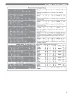
Page 30: ...28 ELECTRICAL CONNECTIONS Figure 7 4 Internal Wiring Schematic ...
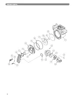
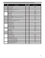
Page 56: ...54 REPAIR PARTS ...
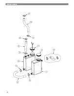
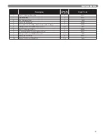
Page 58: ...56 REPAIR PARTS ...
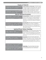
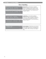
Page 60: ...58 APPENDIX A STATUS SCREENS APPENDIX A STATUS SCREENS ...
Page 61: ...59 APPENDIX A STATUS SCREENS ...
Page 62: ...60 APPENDIX A STATUS SCREENS ...
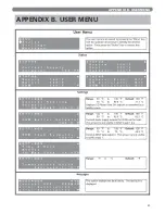
Page 63: ...61 APPENDIX B USER MENU APPENDIX B USER MENU ...
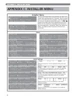
Page 64: ...62 APPENDIX C INSTALLER MENU APPENDIX C INSTALLER MENU ...
Page 65: ...63 APPENDIX C INSTALLER MENU ...
Page 66: ...64 APPENDIX C INSTALLER MENU ...
Page 68: ...66 NOTES ...
Page 69: ...67 NOTES ...


