A. GENERAL
This appliance is to be wired in accordance with local
codes and regulations as defined by the Authority having
jurisdiction. In the absence of such local codes, the
P
URE
F
IRE
boiler is to be wired in accordance with the
latest edition of the National Electrical Code,
ANSI/NFPA 70.
B. CUSTOMER CONNECTIONS
1. Electrical knockouts are provided on the top panel of
the boiler to connect supply wiring, circulator wiring
and wiring to various instruments.
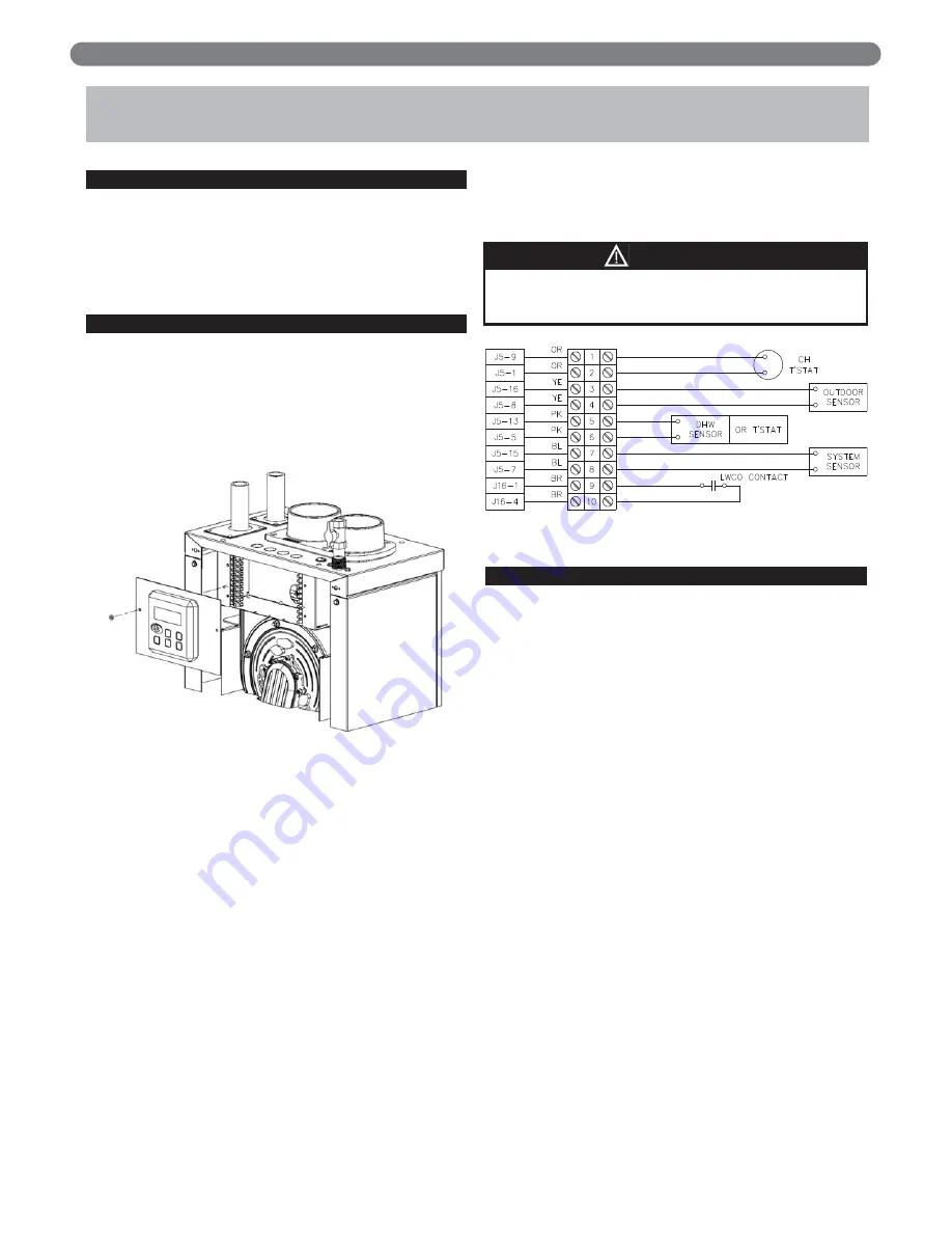
2. Electrical terminals are located behind the User
Interface and can be accessed by loosening the two
nuts shown in Figure 7.1.
a. Remove one of the nuts and leave the other fully
loosened in order to leave the display interface
panel connected to the appliance.
b. The terminals can be removed by gently pulling
them away from their wired blocks. This allows
the installer to easily attach wires to the connector
before plugging it into the block.
3. Figure 7.2 shows the low voltage terminals on the
boiler. These terminals are for customer connection to
the CH thermostat, outdoor sensor*, DHW sensor or
thermostat*, system sensor* and low water cutoff
contact*.
* If used
4. Figure 7.3 shows the line voltage (120 volt) terminals
for customer connection to the DHW, CH, and
General Circulator, the supply voltage, and the low
water cutoff power terminals.
5. Figure 7.3 also shows the wiring of the service switch
and the convenience outlet. Note that the
convenience outlet is powered even when the service
switch is off.
C. INTERNAL WIRING
Figure 7.4 on the following page shows the complete
boiler wiring schematic. The following is a list of internal
wiring components.
1. User Interface: The user interface is attached to the
front of the electrical junction box and is accessible by
removing the tinted lens on the front of the boiler.
This interface allows users and installers to
communicate with the control.
2. Supply Sensor/Limit Switch: This component, located
on the left header is a thermistor that provides
temperature information to the control. Also
incorporated into this component is a high
temperature limit switch that will prevent the boiler
from operating if the supply water temperature is
above 195°F (91°C). Be sure to use only a
P
URE
F
IRE
supply thermister for this boiler.
3. Return Sensor: This thermistor is also located on the
left header toward the rear of the boiler. It provides
return temperature information to the control. Be sure
to use only a
P
URE
F
IRE
return thermistor for this boiler.
4. Flue Sensor: This thermistor provides flue temperature
information to the control. It is located in the back of
the electrical junction box behind the user interface.
5. Condensate Drain Float Switch: This switch is
mounted in the condensate collector below the heat
exchanger in the rear of the cabinet.
6. Service Switch: The service switch interrupts the
power to the
P
URE
F
IRE
boiler to allow service to be
performed.
26
ELECTRICAL CONNECTIONS
7. ELECTRICAL CONNECTIONS
Figure 7.1
Figure 7.2: Low Voltage Customer Connections
The convenience outlet is powered even when the
service switch is off.
CAUTION
Summary of Contents for PF-110
Page 30: ...28 ELECTRICAL CONNECTIONS Figure 7 4 Internal Wiring Schematic ...
Page 56: ...54 REPAIR PARTS ...
Page 58: ...56 REPAIR PARTS ...
Page 60: ...58 APPENDIX A STATUS SCREENS APPENDIX A STATUS SCREENS ...
Page 61: ...59 APPENDIX A STATUS SCREENS ...
Page 62: ...60 APPENDIX A STATUS SCREENS ...
Page 63: ...61 APPENDIX B USER MENU APPENDIX B USER MENU ...
Page 64: ...62 APPENDIX C INSTALLER MENU APPENDIX C INSTALLER MENU ...
Page 65: ...63 APPENDIX C INSTALLER MENU ...
Page 66: ...64 APPENDIX C INSTALLER MENU ...
Page 68: ...66 NOTES ...
Page 69: ...67 NOTES ...


