1 of 13
ISSUED: 11-16-11 SHEET #: 125-9265-2 02-24-12
Visit the Peerless Web Site at www.peerlessmounts.com
For customer care call 1-800-865-2112.
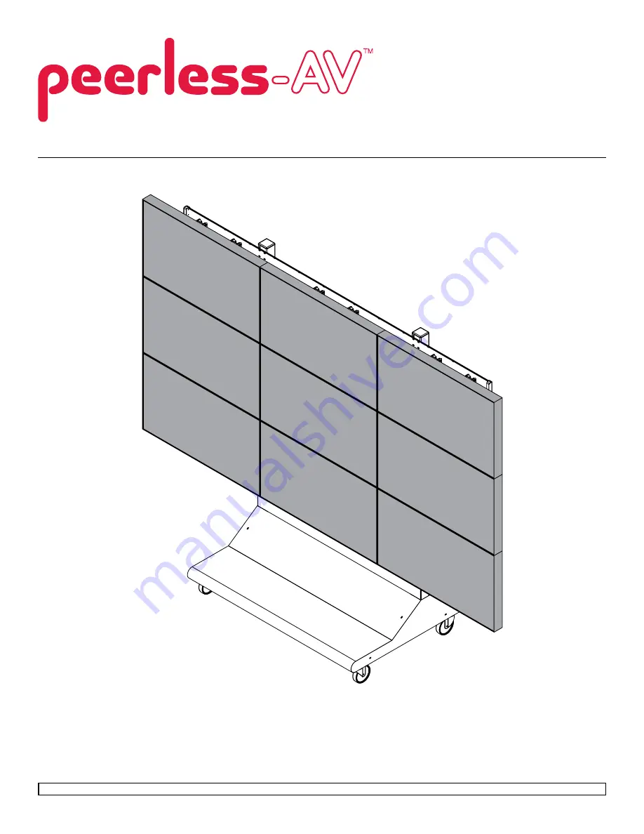
Installation and Assembly: 3 x 3 Cart
Model:
DS-VWC655-3x3
Maximum Load Capacity
1000 Ibs (454 kg)
Page 1: ... 16 11 SHEET 125 9265 2 02 24 12 Visit the Peerless Web Site at www peerlessmounts com For customer care call 1 800 865 2112 Installation and Assembly 3 x 3 Cart Model DS VWC655 3x3 Maximum Load Capacity 1000 Ibs 454 kg ...
Page 2: ...413 L 38 OD x 06 lG nylon washer 36 590 2233 M 18 mesh sleeve 9 600 1014 N M8 x 16 mm phillips screw 36 520 9257 O M6 x 12 mm phillips screw 36 520 1128 P 4 mm allen wrench 9 560 9646 Q cable tie 18 560 9711 R tube cap 2 590 1289 S M5 x 10 mm socket pin screw not used 18 520 1164 T 14 fender washer not used 36 540 1008 U lower front cover 1 145 1505 V lower back cover 1 145 1384 W upper cover 2 14...
Page 3: ...3 of 13 ISSUED 11 16 11 SHEET 125 9265 2 02 24 12 Visit the Peerless Web Site at www peerlessmounts com For customer care call 1 800 865 2112 U V W Y Z AA BB CC DD EE FF X GG ...
Page 4: ...port A using eight 1 4 20 x 3 5 hex head screws J 1 4 SAE washers F and 1 4 20 nylock nuts K 2 Attach horizontal supports C to second vertical support A using eight 1 4 20 x 3 5 hex head screws J 1 4 SAE washers F and 1 4 20 nylock nuts K 3 Attach horizontal support C to vertical supports A using eight 1 4 20 x 3 5 hex head screws J 1 4 SAE washers F and 1 4 20 nylock nuts K A C J F K A C J F K A ...
Page 5: ... 865 2112 4 Attach four swivel casters E to vertical supports A using sixteen M8 x 25 mm pan phillips screws G split washers I and 5 16 SAE flat washers H G I H A E 5 Attach two rail brackets Y together using two rail connection brackets X with eight M5 x 10 mm pan phillips screws AA lock washers CC and flat washers BB X Y AA BB CC ...
Page 6: ... Locate the position of the lower horizontal rail assemblies and attach to vertical supports A 2 Use display height to determine location of upper horizontal rail assemblies NOTE Horizontal rail assemblies must be secured using twenty four 1 4 20 x 3 5 hex head screws J Determine position of horizontal rails assemblies using the formula below 6 UPPER HORIZONTAL RAIL LOWER HORIZONTAL RAIL HORIZONTA...
Page 7: ...ten all 1 4 20 x 3 5 hex head screws J Place two tube caps R into tops of vertical supports A as shown in detail 2 NOTE horizontal rails must be secured using twenty four 1 4 20 x 3 5 hex head screws J A F K J Y A J J DETAIL 2 R CABLE MANAGEMENT 8 Run display cables though top and bottom openings in vertical supports A as shown NOTE Display cables can be covered using 18 mesh sleeve M before secur...
Page 8: ...ss Web Site at www peerlessmounts com For customer care call 1 800 865 2112 9 NOTE Connection brackets GG orientation Place connection brackets GG onto rail connection brackets X as shown below GG FRONT OF DISPLAY CART FRONT OF DISPLAY CART RIGHT SIDE LEFT SIDE X X GG ...
Page 9: ...re call 1 800 865 2112 RIGHT SIDE SHOWN ABOVE AA CC BB GG X Attach connection brackets GG onto rail connection brackets X as shown below Secure one connection brackets GG with four M5 x 10 mm phillips screws AA lock washers CC and flat washers BB as shown below Repeat step for remaining three connection brackets GG 9 1 ...
Page 10: ...ce display is located in desired position tighten security screws as shown in detail 4 10 Attach adapter brackets B to back of display using four M6 x 12 mm phillips screws O or M6 x 16 mm Phillips screw HH with nylon shoulder washer L or four M8 x 15 mm phillips screws N as shown below display B N or O HH L Adapter Bracket Mounting Patterns 11 DETAIL 4 display not shown for clarity TIGHTEN SEcuri...
Page 11: ... 11 SHEET 125 9265 2 02 24 12 Visit the Peerless Web Site at www peerlessmounts com For customer care call 1 800 865 2112 Fasten shelf D onto horizontal support C using three self drilling screws FF as shown below 12 D FF C ...
Page 12: ...end below to determine position of display NOTE Each knob can be adjusted independently for fine tuning angle adjustments Turn knobs CLOCKWISE to raise display height Turn knobs CLOCKWISE to push out display Turn knobs COUNTER CLOCKWISE to lower display height Turn knob COUNTER CLOCKWISE to pull in display UP DOWN IN OUT KNOB Adapter Bracket Adjustment ...
Page 13: ...d V U W V W DD Z A EE DD NOTE Position bottom front and back covers first Position front bottom cover U Secure covers in place using four decorative screws DD as shown below Position back bottom cover V Secure covers in place using four decorative screws DD as shown below Position upper cover W on front of vertical supports A Secure covers in place using four decorative screws DD as shown below Po...