ASSEMBLY OPERATION MAINTENANCE
MANUAL PART#: Q0462
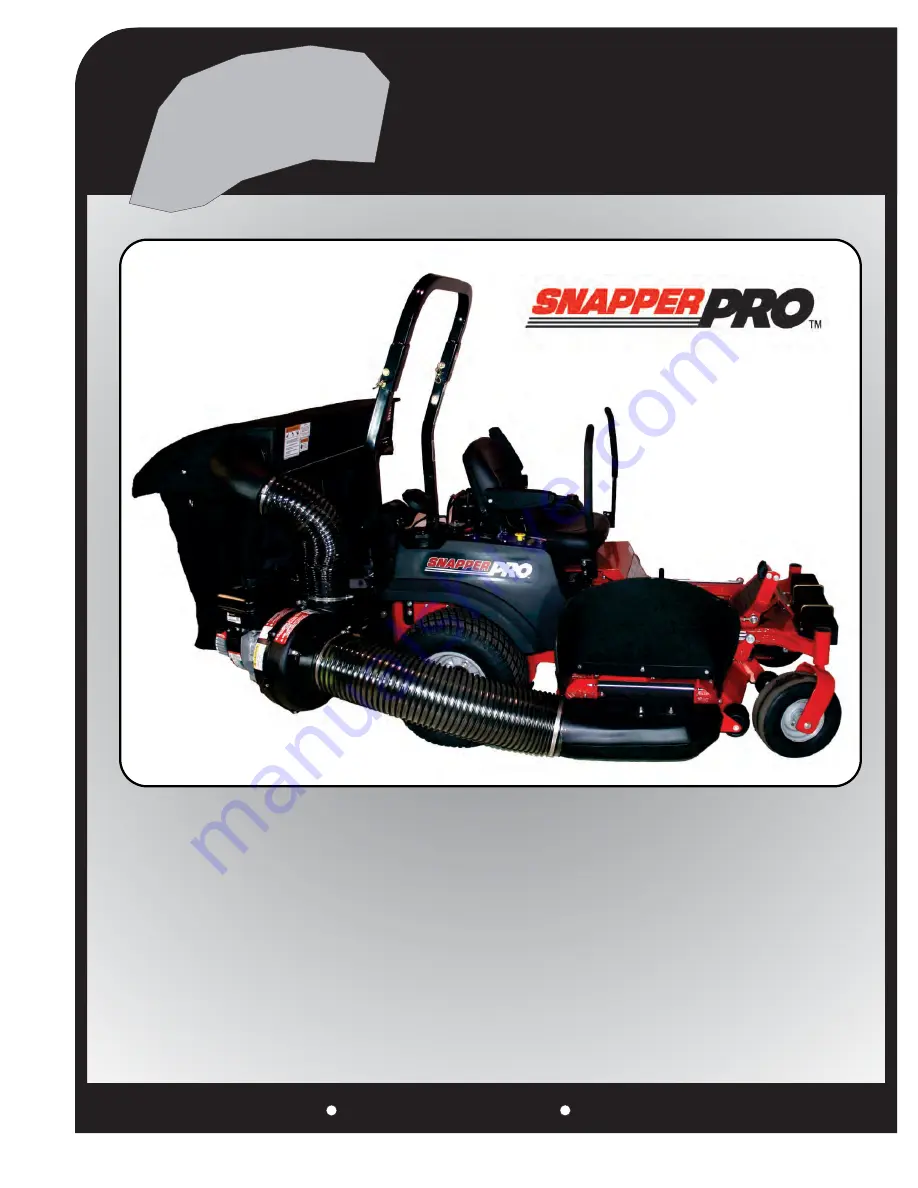
PTO GRASS
COLLECTION
SYSTEM
OPERATOR’S MANUAL
P
PECO
PECO
P
P
P
P
PECO
PECO
PECO
DESIGNED TO FIT:
S150XT
2012-2013
MODEL #: 05131502
900 SERIES BRIGGS & STRATTON
MODEL #: 05131501
6.5HP BRIGGS & STRATTON
VANGUARD


