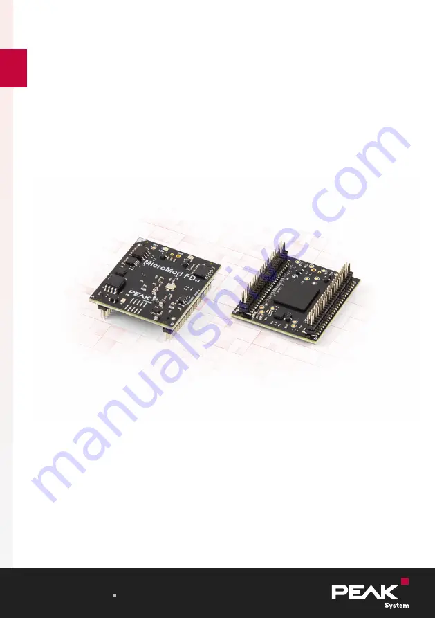
PCAN-MicroMod FD
User Manual
User Manual 1.1.1
© 2020 PEAK-System Technik GmbH
Page 1: ...PCAN MicroMod FD User Manual User Manual 1 1 1 2020 PEAK System Technik GmbH...
Page 2: ...ik GmbH Duplication copying printing or other forms and the electronic distribution of this document is only allowed with explicit permission of PEAK System Technik GmbH PEAK System Technik GmbH reser...
Page 3: ...am 17 4 1 Prerequisites for the Configuration Transfer 17 4 2 Installing the Configuration Program 17 5 Firmware Update 19 6 Technical Specifications 20 Appendix A CE Certificate 23 Appendix B Dimensi...
Page 4: ...Appendix E Changelog User Manual 34 Contents PCAN MicroMod FD User Manual 1 1 1 2020 PEAK System Technik GmbH 4...
Page 5: ...reated on the computer is transferred via the CAN bus to the MicroMod FD which then runs as an independent CAN node Multiple modules can be configured independently on a CAN bus For the PCAN MicroMod...
Page 6: ...3 V Dimensions 33 x 36 mm Extended operating temperature range from 40 to 85 C 40 to 185 F 1 2 Operation Requirements Board with socket strips or hole grid for mounting the PCAN MicroMod FD Evalu ati...
Page 7: ...upply PCAN MicroMod FD plug in board Configuration software for Windows Manual in PDF format Optional Pin adapter for 100 mil pitch 1 Introduction PCAN MicroMod FD User Manual 1 1 1 2020 PEAK System T...
Page 8: ...ossible socket strip 2 pieces as counterpart to the PCAN MicroMod FD Amtek 5PS3MSA44 225GONPNRU 00 On request PEAK System offers an adapter for circuit boards with 100 mil 2 54 mm grid See also Append...
Page 9: ...e external CAN transceiver is used if put on ground A21 Reserved A23 Reserved A25 Reserved A27 Dout 0 Digital outputs 0 to 7 for switching external output drivers 3 3 V level Static state 0 1 PWM at 1...
Page 10: ...d during start up CAN pins A43 A45 A34 Reserved A36 Reserved A38 Reserved A40 Reserved A42 Ext CAN_M1 Connection to alternative external CAN transceiver is enabled by pin A19 A44 Ext CAN_M0 A46 Ext CA...
Page 11: ...e B33 Din 1 B35 Din 2 B37 Din 3 B39 Din 4 B41 Din 5 B43 Din 6 B45 Din 7 B47 3V3in Supply voltage input 3 3 V DC 100 mA connected to B48 B49 GND Ground Pin MMFD Designation Function B2 GND Ground B4 Bo...
Page 12: ...ltage input 3 3 V DC 100mA connected to B47 B50 GND Ground 2 2 Circuitry For the basic operation of the PCAN MicroMod FD a minimal circuitry with the following components is required Voltage supply 3...
Page 13: ...circuit diagram is part of the corresponding user manual PCAN MicroMod FD Evaluation Board Tip When designing the circuitry for the PCAN MicroMod FD also observe the protection against overvoltage and...
Page 14: ...tely No valid config uration Orange quick blinking 4 Hz CAN Bootloader Ready for transfer New firmware can be transferred to the PCAN MicroMod FD via CAN bus using the Windows program PEAK Flash Red o...
Page 15: ...f signal change positive edge negative edge or both edges is set as trigger Digital Outputs A Signal has influence either on the state of a digital output or on the duty cycle at a preset frequency An...
Page 16: ...2 bits max 500 pulses sec Functions A collection of functions that convert one Signal value and place the result on another Signal Excerpt from the collection Mult Mod And Hysteresis Limit RS Flip Fl...
Page 17: ...computer without PCAN environment you can create and edit a configuration with the program and transfer the configuration later to the MicroMod FD using another computer with PC CAN interface 4 2 Ins...
Page 18: ...the instructions of the installation program Retrieve further information about the use of PCAN MicroMod FD Configuration in the provided help that you can reach via the program e g with the F1 key 4...
Page 19: ...PEAK System PEAK Flash for Windows freely available USB B23 Vbus B25 USB1_P B27 USB1_N B6 Binary None mass storage device in operating system Must be connected to ground during switch on Tip In order...
Page 20: ...nd Communication Microcontroller NXP LPC54618 Arm Cortex M4 Core Standard firmware Configuration via reserved CAN ID 7E7h CAN Channels 1 Specification ISO 11898 2 CAN 2 0 A B and CAN FD Transceiver Mi...
Page 21: ...ts Count 8 Functions Static state 0 1 PWM at 1 10 000 Hz common frequency for all outputs Frequency PWM Outputs Count 2 Frequency 20 kHz max Temperature Sensor Design integrated Measuring range 55 125...
Page 22: ...and transport 40 100 C 40 212 F Relative humidity 15 90 not condensing Conformity RoHS EU directive 2011 65 EU RoHS 2 EU directive 2015 863 EU revised list of restricted substances DIN EN IEC 63000 20...
Page 23: ...Appendix A CE Certificate Appendix A CE Certificate PCAN MicroMod FD User Manual 1 1 1 2020 PEAK System Technik GmbH 23...
Page 24: ...ch of connection pins 50 mil 1 27 mm Lower figure example for plug in positioning on a motherboard Possible socket strip 2 pieces as coun terpart to the PCAN MicroMod FD Amtek 5PS3MSA44 225GONPNRU 00...
Page 25: ...r circuit boards with 100 mil 2 54 mm grid The CPU adapter has a circuit board with two socket strips for holding the PCAN MicroMod FD and four pin strips with 100 mil 2 54 mm pitch The latter are sup...
Page 26: ...Pin MMFD Pin Adapter Designation Function A1 a1 GND Ground A3 a2 LED A_red Open drain outputs for external status LEDs A5 a3 LED A_green A7 a4 LED B_red A9 a5 LED B_green A11 a6 FC1_I2C SDA I C 1 ide...
Page 27: ...out 5 A39 a20 Dout 6 A41 a21 Dout 7 A43 a22 CAN H High speed CAN ISO 11898 2 differential signal High A45 a23 CAN L High speed CAN ISO 11898 2 differential signal Low A47 a24 Reset in Module reset Low...
Page 28: ...xt CAN_RxD A50 b25 GND Ground Pin MMFD Pin Adapter Designation Function B1 c1 GND Ground B3 c2 FC0_V24_TxD Serial RS 232 interface for firmware updates B5 c3 FC0_V24_RxD B7 c4 FC0_V24_RTS B9 c5 FC0_V2...
Page 29: ...FD Pin Adapter Designation Function B2 d1 GND Ground B4 d2 Boot Serial Bootloader is started if put on ground during start up RS 232 pins B3 B5 B7 B9 B6 d3 Boot USB USB bootloader is started if put on...
Page 30: ...voltage 3 0 V can be connected to pin B46 as internal reference B46 d23 Vref in Reference voltage input for 12 bit ADC pin B44 recom mended as source B48 d24 3V3in Supply voltage input 3 3 V DC 100mA...
Page 31: ...Height dimension of the CPU adapter including PCAN MicroMod FD Appendix C CPU Adapter for 2 54 mm Pitch PCAN MicroMod FD User Manual 1 1 1 2020 PEAK System Technik GmbH 31...
Page 32: ...d FD Tip The download area for the PCAN MicroMod FD on our website contains additional library files Altium Designer file formats that can be used for simplified integration in own circuit diagrams wi...
Page 33: ...ector Output Pulldown IDx 1 Pullup IDx 0 COBOM1 PIJ101 PIJ102 PIJ103 PIJ104 PIJ105 PIJ106 PIJ107 PIJ108 PIJ109 PIJ1010 PIJ1011 PIJ1012 PIJ1013 PIJ1014 PIJ1015 PIJ1016 PIJ1017 PIJ1018 PIJ1019 PIJ1020 P...
Page 34: ...the 100 mil 2 54 mm pitch on page 25 Diagram for minimum circuitry contains more explaining captions on page 32 LED B of the MicroMod FD indicates invalid configuration with alternating red green bli...