


Microdrive Series Instruction Manual
4201-109 Rev I
28
1.3
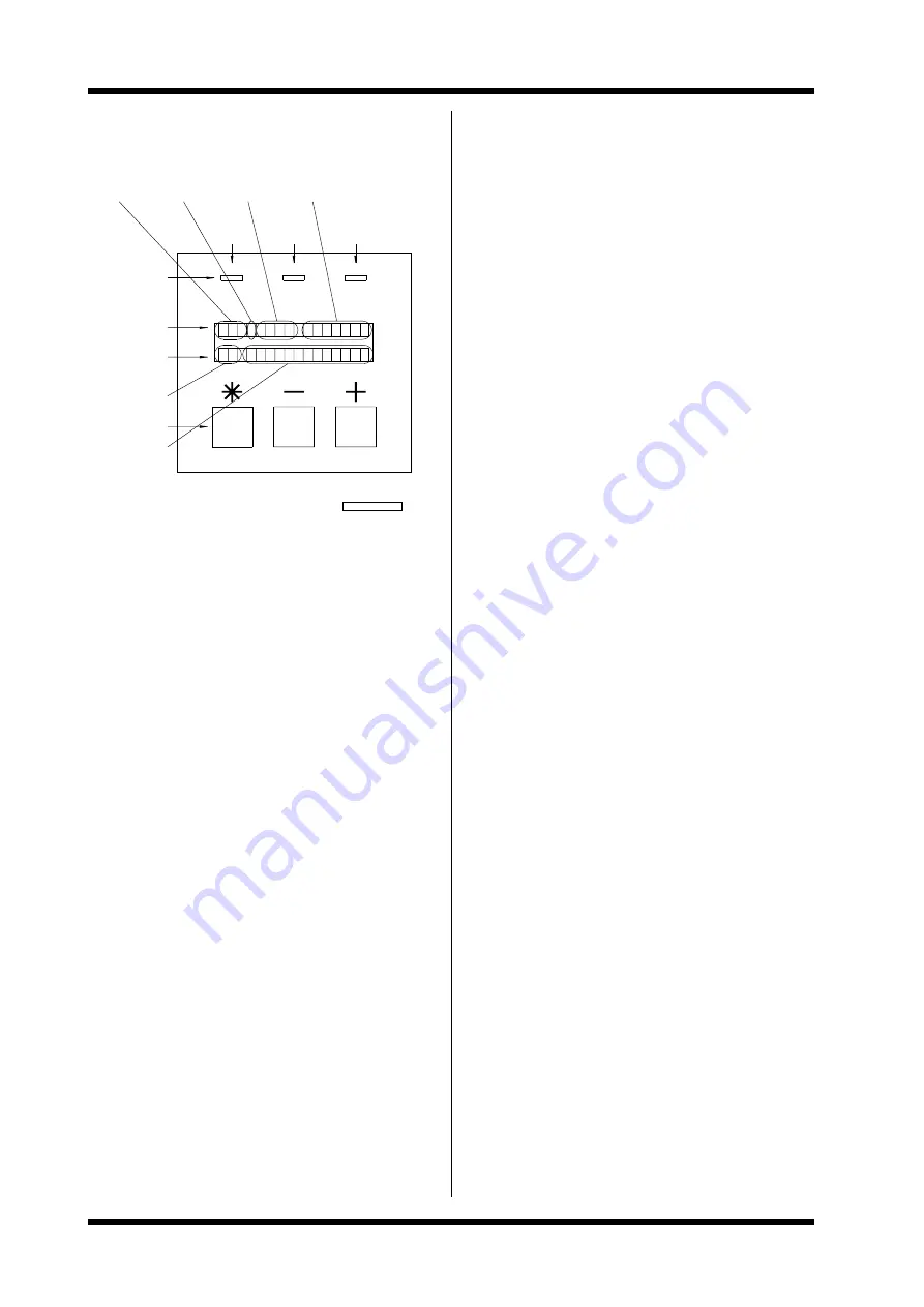
THE CONTROL PANEL
S T P
.
R C U
.
.
(ALWAYS PRESENT)
(SELECTABLE LINE)
4807-024 Rev C
OUTPUT
FREQUENCY
OUTPUT
CURRENT
STATUS
OVERLOAD
(FLASHING)
MESSAGE
STATUS
CONTROL LINE
STATUS LINE
SCREEN
REFERENCE No.
‘SELECT’ KEY
‘-’ KEY
‘+’ KEY
CONTROL KEYS
LED INDICATORS
NO FAULT
(FLASHING = FAULT)
DRIVE
RUNNING
POWER
ON
CONTROL
MESSAGE
SCREEN
RUN
ON
OK
1 0 M T
R = 1 4
9 A
z
H
0
0
+
A
0
0
Figure 1.5
The Control Panel
1.3.1 THE LED INDICATORS
ON
Indicates mains power is supplied to the Microdrive
and stored charge is present
RUN
Indicates the Microdrive is running (driving a motor)
OK
Indicates that the Microdrive is operating normally
OK
Flashing: Indicates that the Microdrive has tripped
on fault protection
1.3.2 USE OF THE CONTROL PANEL
The LCD Display
The Microdrive has a 16 character by two line LCD display.
The lines each have different functions:
-
The STATUS LINE is always present and shows
the Microdrive status, the output current and the
output frequency.
-
The CONTROL LINE display is used to view
and/or adjust the many parameters of the
Microdrive.
Use of the Control Keys
The control keys are used to view and/or adjust the
parameters of the Microdrive.
Screen Selection
-
Use + and to examine the displays.
Notes:
Only the bottom line changes.
Hints:
The reference number tells you which screen you
are on.
Changing a value
-
Use + and to locate the desired screen.
-
Press and hold select to adjust the value.
-
Now use + and to adjust the value.
-
Release select to enter new value.
Hints:
For reasons of security the Microdrive must be in
commission mode (Screen 98) before some
adjustments can be made.
Security Protection
Reaching the commission mode (Screen 98):
Since access to this screen allows any user to adjust all
settings, access is hidden. To access this screen, scroll to
(Screen 97) release and then hold the + button for five
seconds.
1.3.3 SCREEN ORGANISATION
The Microdrive screens are organised in a particular
sequence as shown below.
When delivered the Microdrive is configured to show only
the short menus of the standard configuration (Screen 96
controls this). Only the screens essential for general
applications are shown. All other screens are still active, but
hidden.
Local Control Screens
Screen No.
-3
Function
Input Emulation
Description
Commissioning Check Screen
Screen No.
-2
Function
Keyboard Frequency
Description
Keyboard Frequency Control
Screen
-1
Function
Keyboard Stop/Start
Description
Keyboard Stop/Start Control
Extended Status Screens
Screen No.
0
Function
Primary Screen
Description
General Information Display
Screen No.
1
Function
Secondary Screen
Description
Alternative Information Display
Screen No.
2
Function
Fault Screen
Description
Fault Display Messages
Adjustment Screens
Screen No.
1059
Function
Description
Parameter (Adjustment) Settings
Mode Screens
Screen No.
6094
Function
Description
Mode (Switch) Settings
Screen Controls
Screen No.
95
Function
Language Selection
Screen No.
96
Function
Short/Full Menus
Screen No.
97
Function
Initialisation
Screen No.
98
Function
Commission Mode
Summary of Contents for D3-2.5
Page 2: ...Microdrive Series Instruction Manual 4201 109 Rev I 4201 003 Rev A Page 2 of 12...
Page 6: ...Microdrive Series Instruction Manual 4201 109 Rev I 4201 003 Rev A Page 6 of 12...
Page 12: ...Microdrive Series Instruction Manual 4201 109 Rev I 4201 003 Rev A Page 12 of 12...
Page 55: ...Microdrive Series Instruction Manual 4201 109 Rev I 55...
Page 74: ...Microdrive Series Instruction Manual 4201 109 Rev I 74...
Page 75: ...Microdrive Series Instruction Manual 4201 109 Rev I 75...
Page 76: ...Microdrive Series Instruction Manual 4201 109 Rev I 76...
Page 77: ...Microdrive Series Instruction Manual 4201 109 Rev I 77...
Page 78: ...Microdrive Series Instruction Manual 4201 109 Rev I 78...
Page 79: ...Microdrive Series Instruction Manual 4201 109 Rev I 79...
Page 80: ...Microdrive Series Instruction Manual 4201 109 Rev I 80...
Page 81: ...Microdrive Series Instruction Manual 4201 109 Rev I 81...
Page 82: ...Microdrive Series Instruction Manual 4201 109 Rev I 82...
Page 83: ...Microdrive Series Instruction Manual 4201 109 Rev I 83...
Page 112: ...Microdrive Series Instruction Manual 4201 109 Rev I 112...
Page 113: ...Microdrive Series Instruction Manual 4201 109 Rev I 113...