


Microdrive Series Instruction Manual
4201-109 Rev I
107
APPENDIX 6: TORQUE CONTROL USING THE MICRODRIVE CURRENT LIMIT
the drive if the Microdrive operates in current limit for a
prescribed time. This feature may be useful when the torque limit
is being used for mechanical protection.
In general:
When being used as a torque limiting controller (e.g.,
winder control), current limit mode (Screen 75) should
be set to TQ (torque).
When being used for current limiting, current limit mode
(Screen 75) should be set to I (current).
When attempting to provide very light torque control
(e.g., below 30%) reducing the motor rated voltage
(Screen 11) will improve the sensitivity of control by
increasing the motor current for a given level of torque.
The motor may not then, however, be able to provide full
rated torque should this be required. Alternatively, use
of dynaflux (Screen 25) will make the torque control
become non-linear allowing fine low torque adjustment,
but still provide the possibility of achieving full rated
torque.
When attempting to control a process torque (e.g., web
tension) always ensure that the process torque is much
larger than loss torques (such as the inefficiencies of
gearboxes and drivetrains). Difficulty in control occurs
when a small process torque is to be controlled, but is
dominated by fixed or variable system losses.
CURRENT
INVERTER CURRENT
100%
4807−176 Rev B
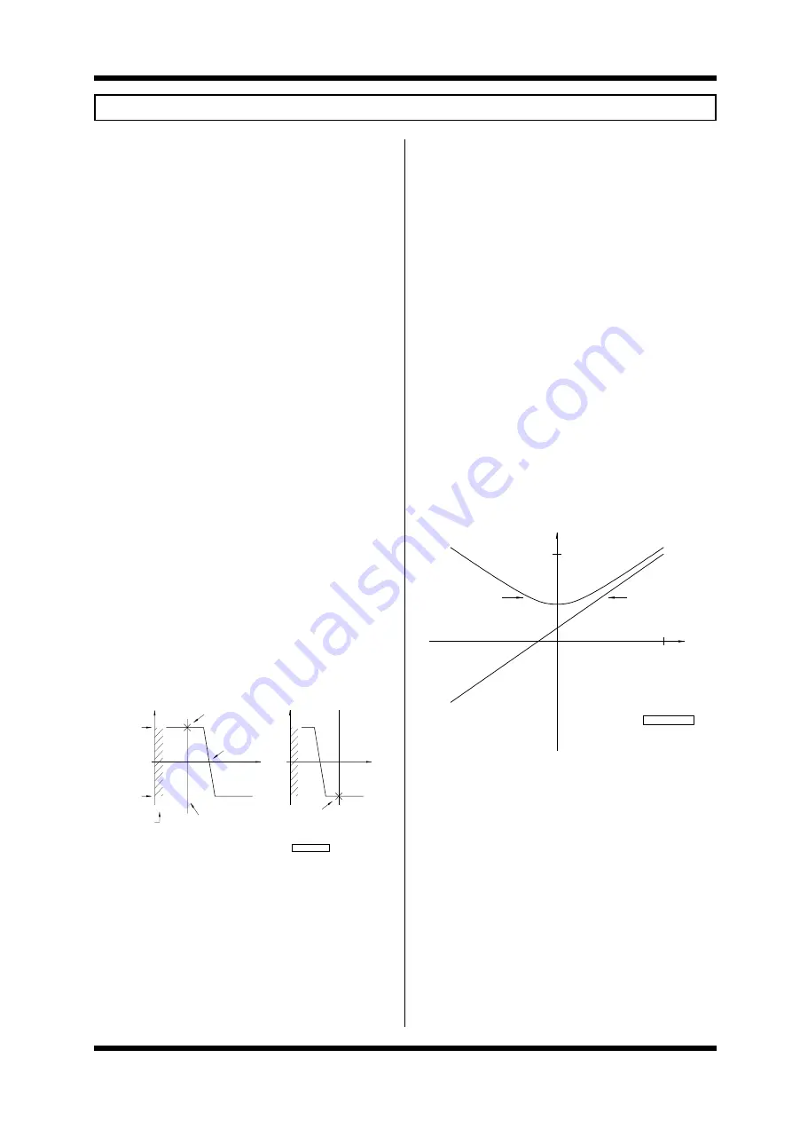
TORQUE CURRENT
TORQUE
100%
6A:
GENERAL NOTES
The Microdrive current limit can be configured as an adjustable
torque limit for many torque sensitive or torque controlled
processes.
The specific load control configuration is programmed via
adjustment Screens 18, 19 and 20 and by mode Screens 75 and
76.
The Microdrive will always operate as a speed controller but the
speed control will be over-ridden when the limiting condition is
encountered (see fig. below). The current limit will operate with
both braking and motoring torques.
If the inverter speed reference is set above that of the process
speed, the inverter will limit in the motoring mode and if the
reference is less than the process then the limit will be in the
braking mode (some means, e.g., a dynamic brake, must be
provided to dissipate the regenerated energy under braking
mode).
The current limit level can be preset to the I LIMIT parameter
(Screen 18) or adjusted via the 420mA or 010V analogue
inputs according to the sources selection (Screen 76), which
provide means of external control.
Torque is only proportional to current when the motor runs with
constant magnetic flux. This means the following conditions
must be met to achieve linear torque control:
-
minimum flux (Screen 25) must be set to 100%.
-
the inverter must be operating in the constant torque
region of operation (i.e., output volts less than or
equal to supply volts).
-
the output frequency must be greater than 3 times
slip frequency.
-
the current limit mode (Screen 75) should be set to
torque.
PROCESS LOAD LINE
(FIXED SPEED)
OPERATING POINT
(MOTORING)
REFERENCE SPEED
+ LIMIT
(ADJUSTABLE)
(ADJUSTABLE)
− LIMIT
TORQUE CONTROL
NOT AVAILABLE
IN THIS REGION
TORQUE
4807−175 Rev B
SPEED
(GENERATING)
OPERATING POINT
TORQUE
SPEED
For best results autoboost (Screen 77) should be selected to
ensure the correct flux is achieved at reduced speeds.
The stability and response of the torque loop is determined by
the ILT SLIP parameter (Screen 20). This is typically set to the
percentage slip of the motor. Reducing this value improves
stability but degrades response time, especially at low
frequencies. If the acceleration and deceleration times are set
too low the response times will also be degraded.
The current limit timeout parameter (Screen 19) can be set to trip
Summary of Contents for D3-2.5
Page 2: ...Microdrive Series Instruction Manual 4201 109 Rev I 4201 003 Rev A Page 2 of 12...
Page 6: ...Microdrive Series Instruction Manual 4201 109 Rev I 4201 003 Rev A Page 6 of 12...
Page 12: ...Microdrive Series Instruction Manual 4201 109 Rev I 4201 003 Rev A Page 12 of 12...
Page 55: ...Microdrive Series Instruction Manual 4201 109 Rev I 55...
Page 74: ...Microdrive Series Instruction Manual 4201 109 Rev I 74...
Page 75: ...Microdrive Series Instruction Manual 4201 109 Rev I 75...
Page 76: ...Microdrive Series Instruction Manual 4201 109 Rev I 76...
Page 77: ...Microdrive Series Instruction Manual 4201 109 Rev I 77...
Page 78: ...Microdrive Series Instruction Manual 4201 109 Rev I 78...
Page 79: ...Microdrive Series Instruction Manual 4201 109 Rev I 79...
Page 80: ...Microdrive Series Instruction Manual 4201 109 Rev I 80...
Page 81: ...Microdrive Series Instruction Manual 4201 109 Rev I 81...
Page 82: ...Microdrive Series Instruction Manual 4201 109 Rev I 82...
Page 83: ...Microdrive Series Instruction Manual 4201 109 Rev I 83...
Page 112: ...Microdrive Series Instruction Manual 4201 109 Rev I 112...
Page 113: ...Microdrive Series Instruction Manual 4201 109 Rev I 113...