background image

Manual 

4.4 

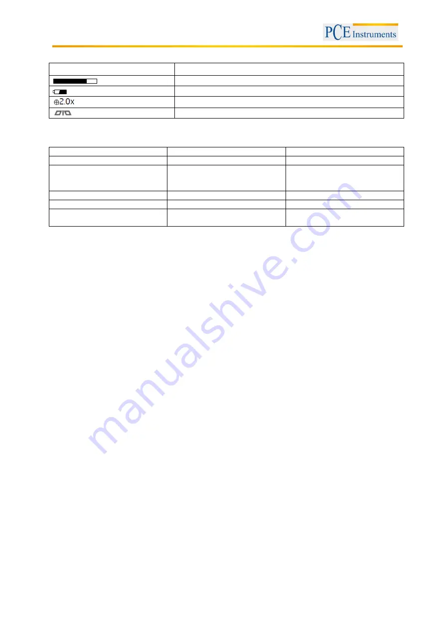
Display indications 

Icon 

Meaning 


Memory capacity of SD card 


Charging level 


2 x zoom active 


Mirror effect active 


4.5 

Handle LED indications 

LED light colour 

Battery status 

Note 

Green 

In use 

Working with full battery 

Dark red 

Low battery 

Please recharge the battery 
when the dark red light appears 
during operation 

Orange 

Charging while in use 

Charging while in use 

Red 

Charging while switched off 

Charging while switched off 

None 

Full battery (while switched off) 

The light turns off as soon as the 
battery is fully charged 


4.6 

How to re-charge the battery 

1. To re-charge the LCD unit only

, plug the mains adaptor into the outlet and insert the jack plug into 

the jack of the LCD unit. 
 

2. To re-charge the LCD unit and the handle simultaneously

, insert the handle into the rear slot of the 

LCD unit (see chapter 4.1) and insert the mains adaptor into the jack at the side of the LCD unit. Connect 
the mains adaptor to a socket. Both devices will now be charged simultaneously. 
 

3. To re-charge the handle bar only

, connect the handle bar to a PC or laptop using a standard mini 

USB cable. 
 

Caution: 

Make sure that the LCD unit and the handle bar are turned off during re-charging and that the 

PC / laptop is on during re-charging via USB cable. Ignore the 

“found new hard drive” message. 


Preparation 

5.1 

Control modes 

 
This device has two control modes 

which are called “direct control” and “wireless control”. 


Direct Control 

Insert the handle bar with the insertion tube into the charging socket located on the back of the LCD unit 
(see chapter 4.1). This will activate Direct Control transmission mode. In this mode, all images are 
transmitted via the wired socket. This can be helpful when working in areas where other high-frequency 
wireless equipment is used as there will be no interference with the video signal. 
 

Wireless Control 

When you disconnect the handle bar from the LCD unit, the device is automatically operated in Wireless 
Control mode. 

Summary of Contents for PCE-VE 500

Page 1: ... UK Ltd Units 12 13 Southpoint Business Park Ensign way Hampshire Southampton United Kingdom SO31 4RF From outside UK 44 Tel 0 2380 98703 0 Fax 0 2380 98703 9 info pce instruments com www pce instruments com english www pce instruments com Manual Version 1 1 Date of creation 15 01 2015 Date of last change 03 05 2016 Automotive Tester PCE VE 5xx Series ...

Page 2: ...ct control 10 6 3 To take pictures 10 6 4 Video recording 10 6 5 To view photos videos 10 6 6 To delete a picture or video in Browse mode only 11 6 7 Zoom In 11 6 8 Mirror 11 7 Settings 11 7 1 Main menu 11 7 2 To delete all files 12 7 3 Video output to activate the AV output 12 7 4 To set up date and time 12 7 5 Language 12 7 6 TV system 13 7 7 Auto power off 13 8 Hyperion camera cable PCE VE 500H...

Page 3: ...n biological sectors for instance for the observation of nests as well as in the archaeological sector The device is delivered with a wireless and removable digital LC display of 3 5 This serves to connect the videoscope to a TV in case you wish to view your target on a larger screen You can also save images or videos on the SD card for further analysis on your PC or laptop Both the videoscope and...

Page 4: ...ice as well as the accessories for visible damage If any damage is visible do not use the equipment Do not use this product in a fuel tank or other dangerous environments such as gasoline or alcohol storage tanks Do not try to disassemble the product as this may cause electric shock and could damage the unit Please use only recommended components or accessories Unapproved components and accessorie...

Page 5: ...r resistant max 1 00 m depth oil and fuel resistant Battery life 4 hours charging time 2 hours Dimensions Handle bar 140 x 35 x 32 mm LC display 147 x 106 x 70 mm Weight Handle b 220g w o insertion tube display 340g Cables Model Cable length Cable type Cable diameter Ø Boost function Illumination PCE VE 500 2000 mm Flexible 5 5 mm No 4 LEDs PCE VE 500HR 2000 mm Flexible 5 5 mm Yes 4 LEDs front 2 L...

Page 6: ...Manual 6 4 System description 4 1 Design ...

Page 7: ... mode Note The system automatically returns from Menu mode to Preview mode after 150 seconds of inactivity 4 3 Keys Key Preview mode Browse mode Menu mode Device switches to Browse mode to view images and videos Move to previous image or video Move one line up Device switches to Browse mode to view images and videos Move to next image or video Move one line down Device switches to Menu mode Play p...

Page 8: ...at the side of the LCD unit Connect the mains adaptor to a socket Both devices will now be charged simultaneously 3 To re charge the handle bar only connect the handle bar to a PC or laptop using a standard mini USB cable Caution Make sure that the LCD unit and the handle bar are turned off during re charging and that the PC laptop is on during re charging via USB cable Ignore the found new hard d...

Page 9: ...2 MHz 3 C 4 2450 MHz 4 8 0 2468 MHz 5 3 To get started 1 Screw the insertion tube into the connector according to the direction of the arrow and tighten the screw nut Figure 1 2 To activate the handle bar with the insertion tube turn the LED adjustment wheel clockwise until you hear a click followed by illumination of the green light Figure 2 3 Push and hold the button of the LCD unit for 3 second...

Page 10: ...e a picture Then push the button to view the picture you have just taken Image status Returns to preview mode after picture is taken 6 4 Video recording 1 Push the button to start video recording Image status Recording time will appear at the left hand bottom side of the display 2 Push the button again to stop recording Image status Recording time disappears 6 5 To view photos videos 1 Push or dur...

Page 11: ... display will show 2 x zoom in view while 2 0 x appears on the right hand bottom side of the display Press ESC again to return to the original view 6 8 Mirror Push and hold the ESC button for 3 seconds to activate mirror view while appears on the right hand bottom side of the display Then push and hold the ESC button for 3 seconds to return to the original view 7 Settings 7 1 Main menu Push the OK...

Page 12: ...V in socket of the external monitor 2 Push OK MENU 3 Push or to move to the video output option 4 Push OK MENU Image status image will be transmitted to the external monitor 7 4 To set up date and time Use the and keys to select Year Month Day or Hour Minute Second Push to increase the number or to decrease Go to DISPLAY and select YES if you wish to have the date on the pictures or NO if you do n...

Page 13: ...s small cables which control the optics and electronics of the camera tip To ensure high reliability do not bend the cable to an angle of more than 90 and store the cable as little bent as possible This product has been produced for industrial use only Do not use it for medical or any other biological purposes Do not use any corrosive agents for cleaning e g alcohol Do not disassemble the device a...

Page 14: ... bend it This can deteriorate your vision and even damage the probe When you roll up the cable the inner diameter must be at least 15 cm Put the protection ring back on and tighten it when not using the device for a longer period of time Do not crash the probe head ...

Page 15: ...ssion oil and water Do not screw the accessories on too tightly Only screw it slightly until it is fixed To clean the camera head use the cleaning liquid and the swabs provided in the cleaning kit 8 2 Technical specifications Length of camera head 20 mm Diameter with protection ring 6 mm Depth of field 10 60 mm Field of view 60 7 Protection IP67 ...

Page 16: ... in dark environments 7 Rotation key Press once to turn the display counter clockwise by 90 The red LED will light up The LED will stop glowing when the original position has been reached 8 Light key This key activates a mirror which enables particle free vision 9 Connection 8 4 Getting started Connection Step 1 Connect the main unit with the connector and fix the connection with a screw nut Step ...

Page 17: ...hread is completely covered Step 4 Align the lateral LED opening of the mirror attachment in a way that the LEDs are uncovered Step 5 Turn the assembly ring upwards in order to fix the mirror attachment Step 6 Press the light key to activate the lateral light Step 7 Adjust the light intensity as required to ensure ideal vision to the side Steps 4 5 must be repeated until the right position is reac...

Page 18: ...aps in Climbing ball Step 1 Remove the assembly ring Step 2 Screw the climbing ball on until it snaps in 8 5 Instructions Boost key Use this key in a dark environment The red LED indicates that the Boost function has been activated The image will be lightened up Note Hold the probe steady Before boosting After boosting ...

Page 19: ...mage by 90 four times for instance when trying to read an inscription completely Light key When using the mirror attachment this key improves the vision which will not be impeded by particles dust etc Without particle free function With particle free function ...

Page 20: ...t the angle Do not try to rotate the rotary switch any further when it has already been rotated all the way to the stop Do not expose the device to extreme temperatures direct sunlight extreme air humidity or moisture Only use the pivoting camera head at temperatures between 0 and 55 C If you coil up the camera cable for storing make sure the diameter is at least 15 cm and that the camera head is ...

Page 21: ...ck 4 Operating unit 5 Rotary switch for gooseneck 6 Connecting cable 7 Connector 8 Locking lever 9 3 Getting started 1 Connect the connecting cable to the display unit of the endoscope and screw it tightly Make sure that the indication on the connector is on the upper side ...

Page 22: ...the right or in a counter clockwise motion to pivot the camera head to the left 2 You can lock the pivoting angle of the camera head by using the red locking lever To lock the camera head carefully push the lever clockwise all the way to the stop To unlock the camera head carefully push the lever counter clockwise until it reaches its starting point ...

Page 23: ... use them or give them to a recycling company which disposes of the devices in line with law If you have any questions please contact PCE Instruments 11 Contact If you have any questions about our range of products or measuring instruments please contact PCE Instruments 11 1 PCE Instruments UK By post PCE Instruments UK Ltd Units 12 13 Southpoint Business Park Ensign Way Southampton Hampshire Unit...

Reviews: