background image

en

17

5.2 

 Basic systems and hydraulic variants

 System 

In addition to the pre-confi gured schemes 881 and 882, the controller is pre-pro-
grammed for 7 basic solar systems. The selection depends on the number of heat 
sources (collector fi elds) and heat sinks (stores, pool). Factory setting is system 1.
The selection of the basic solar system is one of the most important adjustments 
and is thus requested already in the commissioning menu.
First, the basic system is adjusted by means of the number of stores and collectors 
fi elds, then the hydraulic variant.
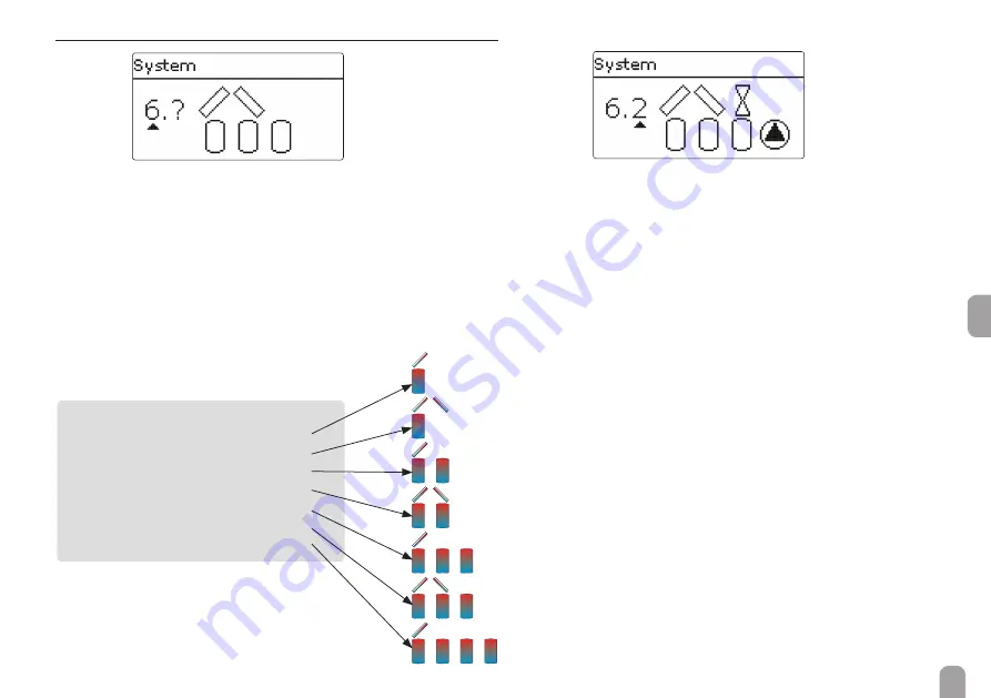
The selected system is visualised by the corresponding number of store and collec-
tor symbols. The fi gure to the left shows system 6 which consists of 3 stores and 2 
collector fi elds (“east- / west collectors”).

A solar system with store charging in layers is 
implemented as a 2-store system (store top = 
store 1; store bottom = store 2).

System 0:  no solar system
System 1:  1 collector fi eld 

-  1 store

System 2:  east- / west collectors  -  1 store
System 3:  1 collector fi eld 

-  2 stores

System 4:  east- / west collectors  -  2 stores
System 5:  1 collector fi eld 

-  3 stores

System 6:  east- / west collectors  -  3 stores
System 7:  1 collector fi eld 

-  4 stores

 Variant 

The hydraulic variant refers to the different actuators that are to be controlled. 
They are visualised on the display by means of symbols, when the variant is select-
ed. The upper symbol indicates the actuator belonging to the collector fi elds, the 
lower one the actuators belonging to the stores.
The  exemplary  fi gure  shows  the  display  indicated  when  system  6,  variant  2  has 
been selected. In this case, each collector fi eld has a 2-port valve, the stores are 
loaded by means of pump logic.

For each variant, the controller allocates the corresponding relays and sensors. The 
allocations of all combinations are shown in chap. 5.3. 

Summary of Contents for SC5.14

Page 1: ...his product Please read this manual carefully to get the best performance from this unit Please keep this manual carefully SC5 14 Manual en Mounting Connection Operation Troubleshooting Application examples Manual for the specialised craftsman ...

Page 2: ...strong electromagnetic fields Subject to technical change Errors excepted Target group These instructions are exclusively addressed to authorised skilled personnel Only qualified electricians should carry out electrical works Initial installation must be effected by the system owner or qualified personnel named by the system owner Description of symbols WARNING Warnings are indicated with a warnin...

Page 3: ... menu 28 7 Status 28 7 1 Solar 28 7 2 Arrangement 28 7 3 Heating 29 7 4 Messages 29 7 5 Meas Balance values 30 7 6 Service 30 8 Solar 30 8 1 Basic solar settings 31 8 2 Solar optional functions 33 8 3 Function control 45 8 4 Solar expert menu 46 9 Arrangement 46 9 1 Optional functions 46 10 Heating 56 10 1 Demands 56 10 2 Heating circuits 56 10 3 Optional functions 59 11 HQM 63 12 Basic settings 6...

Page 4: ... push buttons at the front of the housing Functions DT control pump speed control heat quantity measurement operat ing hours counter for the solar pump tube collector function antifreeze function thermostat function store loading in layers weather compensated heating circuit control priority logic drainback option booster function heat dump function ther mal disinfection function PWM pump control ...

Page 5: ...out the following steps Î Î Unscrew the cross head screw from the cover and remove it along with the cover from the housing Î Î Mark the upper fastening point on the wall Drill and fasten the enclosed wall plug and screw leaving the head protruding Î Î Hang the housing from the upper fastening point and mark the lower fastening points centres 150 mm Î Î Insert lower wall plugs Î Î Fasten the housi...

Page 6: ...For more details about the initial commissioning procedure see page 13 Depending on the product version mains cables and sensor cables are already connected to the device If that is not the case please proceed as follows Temperature sensors S1 to S9 have to be connected to the terminals S1 S9 and GND either polarity Potential free relay Protective conductor common terminal block PE Neutral conduct...

Page 7: ...er is supplied with power via a mains cable The power supply of the device must be 100 240V 50 60 Hz S1 1 2 3 4 5 6 7 8 9 10 11 12 13 14 15 16 S2 S3 S4 S5 S6 S7 S8 R4 R5 IP20 R5 N R1 R4 1 1 A 100 240 V 4 1 A 240V 4 1 A 24V R5 R3 R2 R1 L L Temp Sensor FlowRotor Use neutral conductor common terminal block Use PE Common terminal block Schutzleiter Sammelklemme benutzen RPS S10 V40 PWM1 0 10V PWM2 0 1...

Page 8: ...be carried out Prepare adjustments and parameterisations on a computer 2 Registering sensors If flowmeters flow switches Grundfos Direct Sensors and or external extension modules are connected these have to be registered in the In Outputs menu For further information about the registration of modules and sensors see page 67 3 Activating solar optional functions The basic solar system has been adju...

Page 9: ...a few seconds the display illumination goes out Press any key to reactivate the display illumination Î In order to scroll though a menu or to adjust a value press either buttons and or buttons and Î To open a sub menu or to confirm a value press button Î To enter the status menu press button unconfirmed adjustments will not be saved Î To switch to the previous menu level press button unconfirmed a...

Page 10: ...he new value The new value will be saved if it is confirmed by pressing button again active area inactive area When two values are locked against each other they will display a reduced adjust ment range depending on the adjustment of the respective other value In this case the active area of the slide bar is shortened the inactive area is indicat ed as a dotted line The indication of the minimum a...

Page 11: ...ime frame proceed as follows Î Î Move the cursor to the desired starting point of the time frame by pressing buttons and Confirm the starting point of the time frame by pressing button Î Î Move the cursor to the desired ending point of the time frame by pressing buttons and Î Î The end of a time frame can be determined by pressing button Î Î In order to add another time frame repeat the last three...

Page 12: ...c Optional functions Parallel relay Mixer Store loading Error relay Heating Demands Heating circuits Optional functions Parallel relay Relay Reference relay Overrun Delay Inverted The menu items and adjustment values selectable are variable depending on adjust ments already made The figure only shows an exemplary excerpt of the complete menu in order to visualise the menu structure Basic settings ...

Page 13: ...issioning menu consists of the channels described in the following In or der to make an adjustment push button Adjust the value by pressing buttons and then push button to confirm The next channel will appear in the display 5 5 Adjustment mode button navigation changing a value confirming a value next parameter appears automatically 2 4 1 Language Î Adjust the desired menu language 2 Scheme Î Adju...

Page 14: ...n order to confirm the safety enquiry press but ton Î In order to reenter the commissioning menu channels press button If the safety enquiry has been confirmed the controller is ready for operation and should enable an optimum system operation All adjustments made during commissioning can if necessary be changed later on in the Basic settings menu 7 Selection of the solar system Î Adjust the desir...

Page 15: ...inal block Schutzleiter Sammelklemme benutzen RPS S10 V40 PWM1 0 10V PWM2 0 10V PWM3 0 10V PWM4 0 10V 17 18 19 20 21 22 23 24 25 26 27 28 29 30 31 32 CS10 VBus S9 Relay sensor allocation Connection terminal Description Indication PWM1 Primary pump Speed control signal Primary pump PWM2 Secondary pump Speed control signal Sec ExtHX 1 S1 Collector sensor Collector Flow HQM 1 S2 Store sensor Store 1 ...

Page 16: ...2 23 24 25 26 27 28 29 30 31 32 CS10 VBus S9 SOLEX 2 Scheme 882 In order to select this scheme enter scheme number 882 Relay sensor allocation Connection terminal Description Indication PWM1 Primary pump Speed control signal Primary pump PWM2 Secondary pump Speed control signal Sec ExtHX 1 S1 Collector sensor Collector Flow HQM 1 S2 Store sensor Store 1 S4 Store sensor 2 Store 2 S3 Heat exchanger ...

Page 17: ...ayers is implemented as a 2 store system store top store 1 store bottom store 2 System 0 no solar system System 1 1 collector field 1 store System 2 east west collectors 1 store System 3 1 collector field 2 stores System 4 east west collectors 2 stores System 5 1 collector field 3 stores System 6 east west collectors 3 stores System 7 1 collector field 4 stores Variant The hydraulic variant refers...

Page 18: ...tional function Optional function Optional function Sensor Collector 1 Store base Free Free Free Free Free Free Free System 2 variant 1 S1 S6 R1 R2 S2 Relay sensor allocation 1 2 3 4 5 6 7 8 9 Relay Pump coll 1 Pump coll 2 Optional function Optional function Optional function Sensor Collector 1 Store base Free Free Free Collector 2 Free Free Free ...

Page 19: ...l function Optional function Sensor Collector 1 Store base Free Free Free Collector 2 Free Free Free System 3 variant 1 S1 R2 R1 S2 S4 Relay sensor allocation 1 2 3 4 5 6 7 8 9 Relay Solar pump 3PV Store 2 Optional function Optional function Optional function Sensor Collector Store 1 base Free Store 2 base Free Free Free Free Free ...

Page 20: ...nction Optional function Optional function Sensor Collector Store 1 base Free Store 2 base Free Free Free Free Free System 3 variant 3 R1 R2 R3 S2 S4 S1 Relay sensor allocation 1 2 3 4 5 6 7 8 9 Relay Solar pump 2PV Store 1 2PV Store 2 Optional function Optional function Sensor Collector Store 1 base Free Store 2 base Free Free Free Free Free ...

Page 21: ...ction Optional function Sensor Collector 1 Store 1 base Free Store 2 base Free Collector 2 Free Free Free System 4 variant 2 R1 R2 S1 S6 R3 R4 S4 S2 Relay sensor allocation 1 2 3 4 5 6 7 8 9 Relay Pump coll 1 Pump coll 2 2PV Store 1 2PV Store 2 Optional function Sensor Collector 1 Store 1 base Free Store 2 base Free Collector 2 Free Free Free ...

Page 22: ...ump store 2 Optional function Sensor Collector 1 Store 1 base Free Store 2 base Free Collector 2 Free Free Free System 4 variant 4 R1 R2 S2 S4 R4 S1 S6 R3 Relay sensor allocation 1 2 3 4 5 6 7 8 9 Relay 2PV coll 1 2PV coll 2 Solar pump 3PV Store 1 Optional function Sensor Collector 1 Store 1 base Free Store 2 base Free Collector 2 Free Free Free ...

Page 23: ...function Sensor Collector 1 Store 1 base Free Store 2 base Store 3 base Free Free Free Free System 5 variant 2 S1 R1 R2 R3 S5 S4 S2 Relay sensor allocation 1 2 3 4 5 6 7 8 9 Relay Solar pump store 1 Solar pump store 2 Solar pump store 3 Optional function Optional function Sensor Collector 1 Store 1 base Free Store 2 base Store 3 base Free Free Free Free ...

Page 24: ...or Collector 1 Store 1 base Free Store 2 base Store 3 base Free Free Free Free S1 S2 S4 S5 R1 R3 R2 System 6 variant 1 R1 R2 S6 S1 S2 S4 S5 R5 R4 R3 Relay sensor allocation 1 2 3 4 5 6 7 8 9 Relay Pump coll 1 Pump coll 2 2 PV store 1 2 PV store 2 2 PV store 3 Sensor Collector 1 Store 1 base Free Store 2 base Store 3 base Collector 2 Free Free Free ...

Page 25: ... 3 2PV coll 1 2PV coll 2 Sensor Collector 1 Store 1 base Free Store 2 base Store 3 base Collector 2 Free Free Free System 6 variant 3 Relay sensor allocation 1 2 3 4 5 6 7 8 9 Relay 2PV coll 1 2PV coll 2 Solar pump 3PV Store 1 3PV Store 2 Sensor Collector 1 Store 1 base Free Store 2 base Store 3 base Collector 2 Free Free Free S1 S2 S4 S5 R3 R5 R4 R2 S6 R1 ...

Page 26: ...ptional function Sensor Collector 1 Store 1 base Free Store 2 base Store 3 base Collector 2 Free Free Free System 7 variant 1 S2 S4 S5 S1 S6 R1 R2 R3 R4 R5 Relay sensor allocation 1 2 3 4 5 6 7 8 9 Relay Solar pump 2PV Store 1 2PV Store 2 2PV Store 3 2PV Store 4 Sensor Collector 1 Store 1 base Free Store 2 base Store 3 base Store 4 base Free Free Free ...

Page 27: ...ensor Collector 1 Store 1 base Free Store 2 base Store 3 base Store 4 base Free Free Free System 7 variant 3 Relay sensor allocation 1 2 3 4 5 6 7 8 9 Relay Solar pump store 1 Solar pump store 2 Solar pump store 3 Solar pump store 4 Optional function Sensor Collector 1 Store 1 base Free Store 2 base Store 3 base Store 4 base Free Free Free S1 S2 S4 S5 S6 R1 R2 R3 R4 ...

Page 28: ...pressed for 1 min the display illumination goes out After 3 more minutes the controller switches to the Status menu Î In order to get from the Status menu into the Main menu press button 7 Status In the Status menu of the controller the status messages for every menu area can be found 7 1 Solar In the Status Solar menu the status of the solar system the solar loading and the selected optional func...

Page 29: ...eak Sensor line broken 0002 Sensor fault Sensor short circuit Sensor line short circuited 0011 DT too high DT too high Collector 50 K than store to be loaded 0021 Night circulation Night circulation Betw 11 p m and 5 a m col temp 40 C 0031 FL RE inter changed FL RE interchanged Col temp does not rise after switching on 0041 Flow r monit Flow rate monitoring No flow rate at sensor 0051 Overpressure...

Page 30: ...ement value is selected another sub menu will open If for example S1 is selected a sub menu indicating the minimum and maximum values will open When the item Chart is selected a progression chart appears The progression chart shows the development of the temperature at the corre sponding sensor over the last 24 hours Press buttons and to switch back and forth between a chart of the current day and...

Page 31: ...tem and variant have usually been adjusted during commissioning If the setting is changed later on all adjustments for the solar part of the arrangement are set back to their factory settings If the change causes the solar system to require a relay that has been allocated to an arrangement function before all adjustments made in the non solar function will be set back to their factory settings as ...

Page 32: ...justment channel Description Adjustment range selection Factory setting Load break Loading break time 1 5 2 Circ Circulation time 1 60 15 Pause speed Pause speed Yes No No Speed Pause speed 20 30 100 30 Pump del Pump delay Yes No No Delay Delay time 5 600s 15 s In systems with 2 or more stores loading logic adjustments can be made in this menu In systems 1 and 2 only the menu item Pump delay will ...

Page 33: ... are available for selection In the sub menu Controller all free relays of the controller are displayed If ex ternal modules are connected and registered their relays will be displayed in cor responding sub menus When a function has been selected and adjusted it will appear in the Opt func tions menu above the menu item Add new function This allows an easy overview of functions already activated A...

Page 34: ...k is diverted through a bypass past the store Once the pipe is warm enough the store can be loaded The switch on conditions can be adjusted individually Solar Opt functions Add new function Bypass Adjustment channel Description Adjustment range selection Factory setting Collector Collector field system dependent system dependent Relay Bypass relay system dependent system dependent Variant Variant ...

Page 35: ...respective maximum temperatures Variant valve Variant pump Exemplary schematics for the bypass variants Bypass sensor Relay Bypass sensor Relay Variant valve inverted Bypass sensor Relay Depending on whether the bypass is energised by a valve or by a second pump a corresponding adjustment can be made in the menu item Variant Depending on the variant different control logics are applied Pump In thi...

Page 36: ...an 10 seconds the pump will be run at 100 for the first 10 s of the runtime For the remaining runtime the pump will be run at the adjusted minimum speed If the collector sensor is defective or the collector is blocked this function is sup pressed or switched off 2 collector systems In 2 collector systems the tube collector function is available for each individual collector field If one of the col...

Page 37: ... protection collector Solar Opt functions Add new function Antifreeze Adjustment channel Description Adjustment range selection Factory setting Frost on Antifreeze switch on temperature 40 15 C 4 C Frost off Antifreeze switch off temperature 39 16 C 6 C Collector Collector field system dependent system dependent Store 1 4 Store succession order system dependent system dependent Funct Activation De...

Page 38: ...up pressed when the store temperature exceeds the Set temperature Parallel relay Solar Opt functions Add new function Parallel relay Adjustment channel Description Adjustment range selection Factory setting Relay Parallel relay system dependent system dependent Store Store sensor selection system dependent system dependent Funct Activation Deactivation Activated Deactivated Deactivated With this f...

Page 39: ...r loading on the following day When the store cooling function is activated the solar pump is switched on if the maximum store temperature is exceeded and the collector temperature falls below the store temperature The solar pump remains active until the store tem perature falls below the adjusted maximum store temperature The store order for the cooling is the same as in the overheating through s...

Page 40: ...ar stores can be selected The relay is switched off if this temperature difference falls below the adjusted switch off difference In contrast to the bypass function a differential control between Sen Ext HX and the store temperature can be carried out by means of the heat exchanger relay The reference sensor can be arbitrarily allocated In systems in which stores are equipped with their own loadin...

Page 41: ...y be activated if all components required are properly installed The parameter Filling time is used for adjusting the time period for which the pump will be run at 100 speed in order to fill the system The parameter Stab time is used for adjusting the time period during which the switch off condition will be ignored after the filling time has ended The parameter Initialis is used for adjusting the...

Page 42: ...he flow rate monitoring op tion is activated two additional adjustment channels appear for allocating a sensor and adjusting a delay time If the flow rate monitoring option is activated an error message will appear when no flow rate is detected at the allocated sensor after the Delay time has passed The active relay is considered as defective and will be blocked until the error mes sage has been a...

Page 43: ...Solar Basic settings Store menu the heat dump function is released again Variant pump Variant valve Flow rate monitoring Solar Opt functions Add new function Flow rate mon Adjustment channel Description Adjustment range selection Factory setting Sensor Flow rate sensor selection Imp1 Flowrotor Reference relay Reference relay selection system dependent Store Store sensor selection system dependent ...

Page 44: ...ill only be available when an RPS type Grundfos Direct Sensor or an electronic pressure gauge is connected Overpressure If the system pressure exceeds the adjustable switch on value On an error mes sage will appear If the shutdown option has been activated for the overpressure monitoring func tion the solar system will be shut down as well in the case of a fault condition When the pressure reaches...

Page 45: ...ature exceeds 40 C the temperature difference exceeds DTon The delay time of 1 min ensures that the message is not triggered by short term fault conditions Possible causes are defective non return valves defective valve wrongly adjusted time Flow and return pipe interchanged This function is used for detecting an interchange of the flow and return pipe or a badly placed collector sensor For this p...

Page 46: ...he special hydraulics in systems with 2 collectors this func tion will not work properly there Flow sensor Return sensor Example of flow and return sensor positions 9 Arrangement In this menu all adjustments for the non solar part of the arrangement can be made A range of optional functions can be selected and adjusted 9 1 Optional functions In this menu additional functions can be selected and ad...

Page 47: ...rview about which sensor has been allocated to which component and which relay has been allocated to which function is given in the Status Service menu At the end of each optional function sub menu the menu items Function and Delete function are available With the menu item Function an optional function already selected can be tem porarily deactivated or re activated respectively All adjustments r...

Page 48: ...er the ad justed delay time has expired If the reference relay is switched off again during the delay time the parallel relay will not be switched on at all If the Inverted option is activated the parallel relay switches on when the refer ence relay switches off and vice versa Note If a relay is in the manual mode the selected parallel relay will not be energised Mixer Arrangement Opt functions Ad...

Page 49: ...ers If the measured temperatures at both allocated sensors fall below the adjusted switching threshold TBoiler on the relay is energised It is switched off again when the temperature at both sensors has exceeded TBoiler off If one of the two sensors is defective store loading is suppressed or switched off When the Timer option is activated a timer is indicated in which time frames for the function...

Page 50: ...ction All days Monday Sunday Continue Timer Time frame adjustment 00 00 23 45 Funct Activation Deactivation Activated Deactivated Deactivated The Heat exchange function can be used for transferring heat from a heat source to a heat sink The allocated relay is energised when all switch on conditions are fulfilled the temperature difference between the allocated sensors has exceeded the switch on te...

Page 51: ...elay Solid fuel boiler Arrangement Opt functions Add new function Solid fuel boiler Adjustment channel Description Adjustment range selection Factory setting Relay Relay selection system dependent system dependent Sen Boiler Solid fuel boiler sensor selection system dependent system dependent Sen Store Store sensor selection system dependent system dependent DTon Switch on temperature difference 1...

Page 52: ...function Circulation Adjustment channel Description Adjustment range selection Factory setting Relay Relay selection system dependent system dependent Type Variant Demand Thermal Timer Therm Timer Demand Timer Thermal Sensor Circulation sensor selection system dependent system dependent Ton Switch on temperature 10 59 C 40 C Toff Switch off temperature 11 60 C 45 C Timer Timer Days of the week Day...

Page 53: ... Activated Deactivated Deactivated When a heating circuit has been activated the value adjusted in the corre sponding parameter in the heating circuit menu is adopted as factory setting The Return preheating function can be used for transferring heat from a heat source to the heating circuit return The allocated relay is energised when both switch on conditions are fulfilled the temperature differ...

Page 54: ...d off as soon as the adjusted switch off temperature difference DTh x off is reached The switching conditions of all other activated functions of the function block have to be fulfilled as well The DT function is equipped with a speed control function A set temperature dif ference and a minimum speed can be adjusted The non adjustable rise value is 2K Reference relay Up to 5 reference relays can b...

Page 55: ...5 Reference relay Reference relay Yes No No Mode Reference relay mode OR AND OR Relay Reference relay 1 all relays Relay Reference relay 2 all relays Relay Reference relay 3 all relays Relay Reference relay 4 all relays Relay Reference relay 5 all relays Funct Activation Deactivation Activated Deac tivated Activated Relays that have been selected as parallel relays in the optional functions Solar ...

Page 56: ...ion modules are connected they have to be registered with the controller Only registered modules are available in the heating circuit selection In the menu appearing when New heating circuit is selected it is possible to choose between the internal heating circuits and if available registered modules Extension modules can be registered in the In Outputs Modules menu see page 71 If an internal or e...

Page 57: ... Both has been selected in the Mode channel the summer tem perature TSummer can be adjusted If the outdoor temperature exceeds the value adjusted in TSummer the heating circuit pump is switched off Outdoor temperature in C Flow temperature in C Heating curves For the summer temperature a daytime time frame can be adjusted with the chan nels Daytime on and Daytime off Outside this time frame the ad...

Page 58: ...cuits New heating circuit Internal Adjustment channel Description Adjustment range selection Factory setting HC pump Heating circuit pump system dependent system dependent Mixer open Relay selection mixer open system dependent system dependent Mixer closed Relay selection mixer closed system dependent system dependent Flow sensor Flow sensor selection system dependent system dependent Sensor Outdo...

Page 59: ...function can be used for enabling a quick access to measure ment conditions without menu operation for the chimney sweeper If the chimney sweeper function is activated the chimney sweeper mode can be accessed by pressing button for 5 seconds In the chimney sweeper mode the heating circuit mixer opens the heating circuit pump and the afterheating contact are activated While the chimney sweeper mode...

Page 60: ...nc tions menu above the menu item Add new function This allows an easy overview of functions already activated An overview about which sensor has been allocated to which component and which relay has been allocated to which function is given in the Status Service menu At the end of each optional function sub menu the menu items Function and Delete function are available With the menu item Function...

Page 61: ...toring period begins Due to the flexible control logic the exact time of thermal disinfection is not predictable In order to set a fixed time for the disinfection the starting delay can be used Heating Opt functions Add new function Th disinfection Adjustment channel Description Adjustment range selection Factory setting Dem Demand relay selection system dependent system dependent Circulating pump...

Page 62: ... another adjustment channel appears in which a relay can be allocated to the loading pump The allocated relay is switched on and off with the demand relay If the Overrun time option is activated another adjustment channel appears in which the overrun time can be adjusted If the overrun time option is activated the loading pump relay remains switched on for the adjusted Duration after the demand re...

Page 63: ...ive In the adjustment channel Fluid type the heat transfer fluid must be selected If either Propylene glycol or Ethylene glycol is selected the adjustment channel Ratio is indicated in which the antifreeze ratio of the heat transfer fluid can be adjusted When the Alternative unit option is activated the controller will convert the heat quantity into the quantity of fossil fuels coal oil or gas sav...

Page 64: ...lternative display unit Coal Gas Oil CO2 CO2 Factor Conversion factor 0 0000001 100 0000000 0 5000000 Funct Activation Deactivation Activated Deactivated Deactivated 12 Basic settings Basic settings Adjustment channel Description Adjustment range selection Factory setting Language Selection of the menu language Deutsch English Français Italiano Español German Auto DST Daylight savings time selecti...

Page 65: ...C514 on the SD card and extract the down loaded ZIP file into this folder Starting the logging Î Insert the SD card into the slot Î Adjust the desired logging type and interval Logging will start immediately Stopping the logging Î Select the menu item Remove card Î After Remove card is displayed remove the card from the slot When Linear is adjusted in the Logging type adjustment channel data loggi...

Page 66: ...ax Auto Min Off Auto All relays Operating mode of all relays Auto Off Off In the Manual mode menu the operating mode of all relays in the controller and in connected modules can be adjusted All relays are displayed in numerical order first those of the controller then those of the individual modules connected Modules are listed in numerical order In the menu item All relays all relays can be switc...

Page 67: ...Customer user code 0000 16 In Outputs In the In Outputs menu external modules can be registered sensor offsets can be adjusted and relay outputs can be configured 16 1 Modules In this menu up to 2 external modules can be registered All modules connected and acknowledged by the controller are available Î To register a module select the corresponding menu item by pressing button The checkbox indicat...

Page 68: ...ade To carry out the offset proceed as follows Î Adjust the CS type in the Type channel Î Select the Offset channel Î Confirm the reset enquiry by selecting Yes Î Select back to return to the Inputs menu then connect the CS sensor Note When Grundfos Direct SensorsTM are used the sensor ground common terminal block must be connected to PE see controller manual In Outputs Inputs Adjustment channel D...

Page 69: ...controller is equipped with a relay overrun function that automatically comes into effect when the speed control signal is not issued by the relay itself The cor responding relay will then remain switched on for an hour after the switch off conditions are fulfilled In Outputs Outputs Adjustment channel Description Adjustment range selection Factory setting R1 R5 Relay output selection Signal Signa...

Page 70: ...70 en 16 4 PWM profiles Signal characteristic PWM Profile Solar PWM 0 12 7 95 100 min max H Signal characteristic PWM Profile Heating PWM 0 5 93 88 85 100 min max H ...

Page 71: ...e controller could be blown The fuse holder which holds the spare fuse becomes accessible when the cover is removed The fuse can then be replaced Check the power supply of the controller Is it disconnected no yes C F Ω Pt500 Ω Pt1000 Ω KTY C F Ω Pt500 Ω Pt1000 Ω KTY 10 14 481 961 1499 55 131 607 1213 2502 5 23 490 980 1565 60 140 616 1232 2592 0 32 500 1000 1633 65 149 626 1252 2684 5 41 510 1019 ...

Page 72: ... the heat Collector circuit pump defective no yes Heat exchanger calcified yes Check replace it Decalcify it no Heat exchanger blocked yes no Clean it Heat exchanger too small yes Change Ton and Toff corre spondingly Switch on temperature difference Ton too large no yes Vent the system increase the sys tem pressure to a static primary pressure of at least plus 0 5 bar if necessary continue to incr...

Page 73: ...losses now o k yes yes no a no Collector temperature at night is higher than the outdoor temperature no no yes Controller might be defective replace it Is the pump stuck Turn the pump shaft using a screw driver now passable Pump is defective replace it yes no Does the DHW circulation run for a very long time no yes Use the circulation pump with timer and switch off thermostat energy efficient circ...

Page 74: ...OL controllers with RESOL VBus It is used for visualising data issued by the controller collector temperature store temperature and energy yield of the solar thermal system The use of high efficiency LEDs and filter glass assures a high optical brilliance An addi tional power supply is not required One module is required per controller The RESOL GA3 is a completely mounted large display module for...

Page 75: ... directly to a PC or router for remote access and thus enables comfortable system monitoring for yield monitoring or for diagnostics of faults DL3 Datalogger Be it solar thermal heating or DHW heat exchange controllers with the DL3 you can easily and conveniently log system data of up to 6 controllers Get a com prehensive overview of all controllers connected with the large full graphic display Tr...

Page 76: ... External heat exchanger solar optional function 40 F Flow rate monitoring 43 Formatting the SD card 65 Function block 54 Fuse replacing of 71 H Heat dump 42 Heat exchange 50 Heating circuits internal 56 Heating demands 56 Heat quantity measurement 63 I Irradiation switch 55 M Mains connection 7 Manual mode 66 Maximum store temperatures 32 Measured values 30 Minimum collector limitation 31 Mixer o...

Page 77: ...40 Solid fuel boiler 50 Store cooling Cooling mode 39 Store loading 49 Store set temperature 32 Storing controller adjustments 65 System cooling Cooling mode 39 45 T Target temperature solar optional function 37 Technical data 4 Thermal disinfection 61 Thermostat function 54 Tube collector function 36 Twin pump 42 U User code 67 ...

Page 78: ...en 78 ...

Page 79: ...en 79 ...

Page 80: ...80 en Distributed by PAW GmbH Co KG Böcklerstraße 11 31789 Hameln Tel 49 0 51 51 98 56 0 Fax 49 0 51 51 98 56 98 www paw eu info paw eu All contents of this document are protected by copyright ...

Reviews: