


Reviews:
No comments
Related manuals for PATRON series

3 Series
Brand: Campingaz Pages: 28

3 Series
Brand: Campingaz Pages: 38
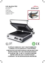
PRO
Brand: Lacor Pages: 88

E600
Brand: Falcon Pages: 12
501
Brand: Oliver Pages: 33
2000
Brand: IGF Pages: 32
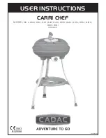
8100
Brand: Cadac Pages: 13
8100
Brand: dancook Pages: 16

2 Series
Brand: Campingaz Pages: 108

XL
Brand: Panini Pages: 6
XL
Brand: Jata electro Pages: 20
25331
Brand: Hamilton Beach Pages: 32

25357
Brand: Hamilton Beach Pages: 24

1003
Brand: Callow Pages: 8

Compact
Brand: OBH Nordica Pages: 44

800
Brand: Landmann Pages: 48

Gas Grill
Brand: Napoleon Pages: 24

JGGN24
Brand: GE Pages: 28


