USERMANUAL
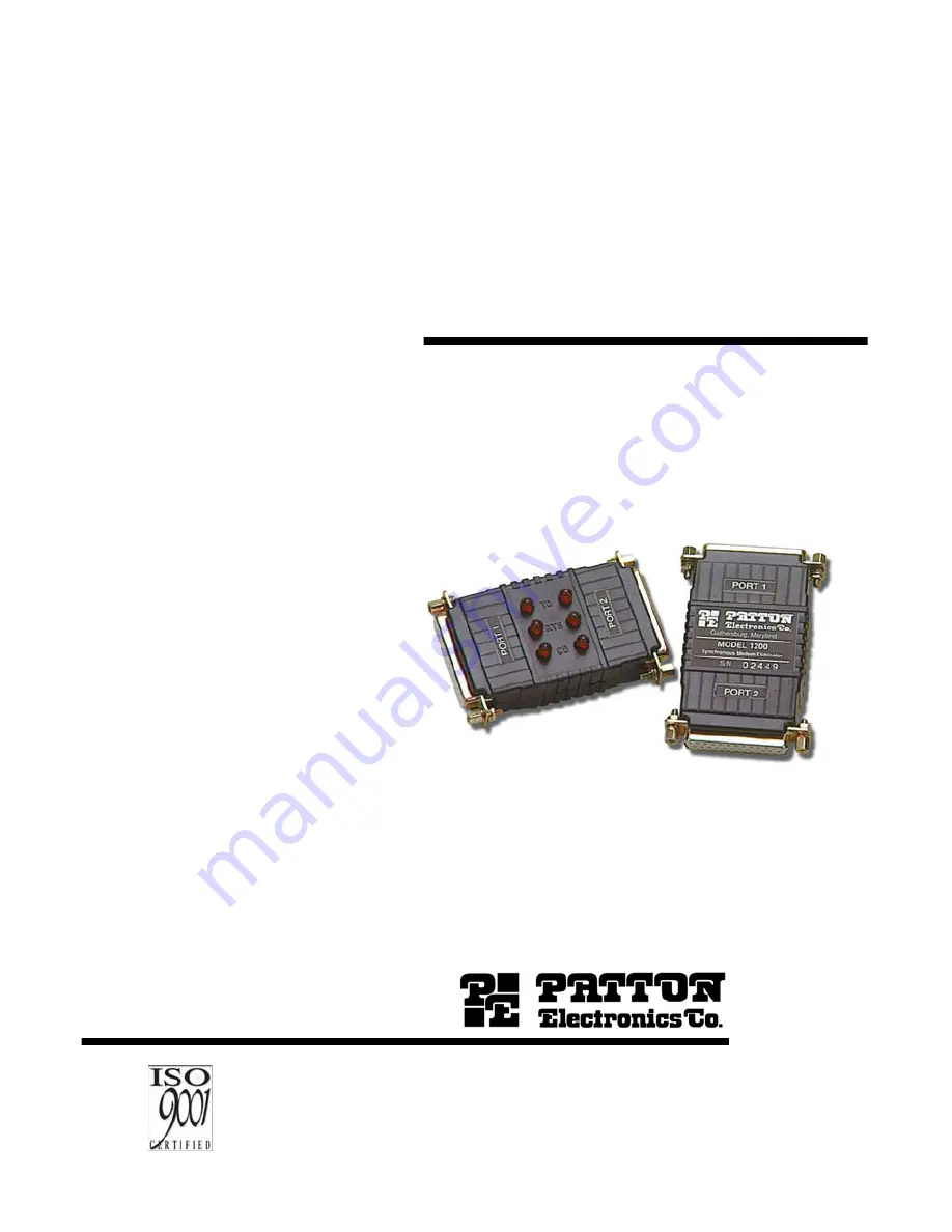
MODEL 1200/1201
Synchronous Modem Eliminator
SALES OFFICE(301) 975-1000TECHNICAL SUPPORT(301) 975-1007
P/N: 07M1200-CDoc# 049011U,Rev. DRevised 1/22/08
An ISO-9001
Certified
Company
Page 1: ...USER MANUAL MODEL 1200 1201 Synchronous Modem Eliminator SALES OFFICE 301 975 1000 TECHNICAL SUPPORT 301 975 1007 P N 07M1200 C Doc 049011U Rev D Revised 1 22 08 An ISO 9001 Certi ed Company...
Page 2: ...1 Data Rate 9 4 2 Carrier Detect 9 4 3 RTS CTS Delay 10 4 4 Ground 10 5 0 Operation 11 5 1 LED Status Indicators Model 1201 only 11 A Specifications 12 A 1 Data Rates 12 A 2 Clocking 12 A 3 Grounding...
Page 3: ...this product shall be deemed an acceptance of these terms by the user In the event the user detects intermittent or continuous product malfunction due to nearby high power transmitting radio frequenc...
Page 4: ...All warranty and nonwarranty repairs must be returned freight prepaid and insured to Patton Electronics All returns must have a Return Materi als Authorization number on the outside of the shipping co...
Page 5: ...nly 2 2 DESCRIPTION Measuring only 5 3 x 2 x 1 2 inches the Patton Model 1200 is the small est self powered synchronous modem eliminator on the market All power is derived from the RS 232 data signals...
Page 6: ...ter or device to which the Model 1200 is to be connected 3 Plug the DB 25 connectors directly into the serial ports of your RS 232 devices If you wish to extend the distance you can add cables on both...
Page 7: ...locking is selected the Model 1200 will automatically match the clocking between your two synchro nous devices The default setting is 9 6 Kbps 4 2 CARRIER DETECT The carrier detect straps allow you to...
Page 8: ...er to emulate either dial up or leased line modems you can set this strap at either no delay 6 6mS or 53mS Port 1 and port 2 may be con gured separately The default setting is 6 6mS for both ports 4 4...
Page 9: ...ived from the RS 232 data and control signals there is no ON OFF switch 5 1 LED STATUS INDICATORS MODEL 1201 ONLY The Model 1201 features six front panel status LEDs that indicate the condition of the...
Page 10: ...es and decreases for higher bit rates A 5 FUNCTIONAL Emulates half or full duplex dial up or dedicated line A 6 RTS CTS DELAY Selectable per port 0mS 6 6mS 53mS A 7 DCD Selectable per port continuous...
Page 11: ...11 APPENDIX B BLOCK DIAGRAM Copyright 2001 Patton Electronics Company All Rights Reserved...
Page 12: ...his product and how we can meet your prod uct needs today and in the future Web http www patton com Sales E mail sales patton com Support E mail support patton com Phone Sales 301 975 1000 Phone Suppo...