USERMANUAL
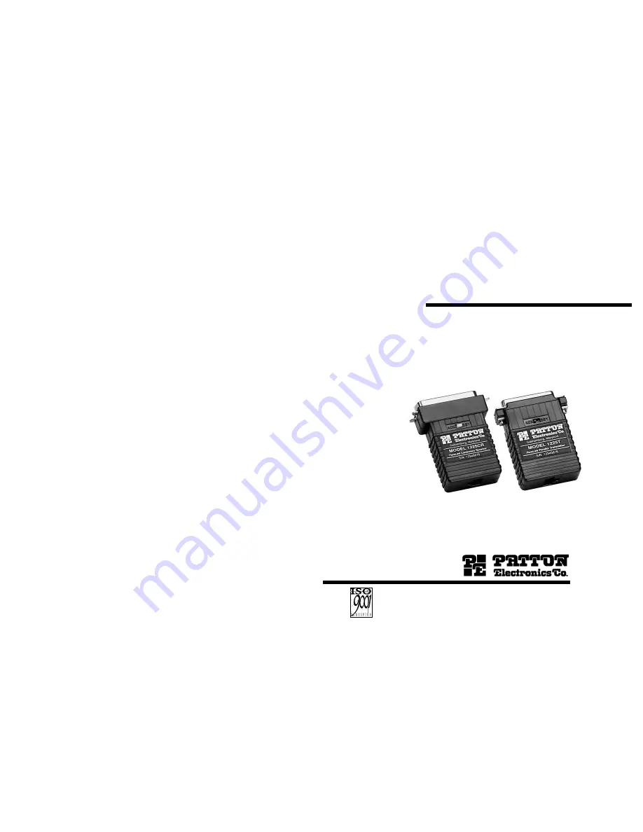
MODEL 1225
ParaLink
TM
Parallel
Short Range Modem
SALES OFFICE(301) 975-1000TECHNICAL SUPPORT(301) 975-1007http://www.patton.com
Part #07M1225-BDoc. #104011UBRevised 9/12/97
C E R T I F I E D
An ISO-9001
Certified Company
Page 1: ...DEL 1225 ParaLinkTM Parallel Short Range Modem SALES OFFICE 301 975 1000 TECHNICAL SUPPORT 301 975 1007 http www patton com Part 07M1225 B Doc 104011UB Revised 9 12 97 C E R T I F I E D An ISO 9001 Certified Company ...
Page 2: ...lation However there is no guarantee that interference will not occur in a particular installation If the Model 1225 does cause interference to radio or television reception which can be determined by disconnecting the Model 1225 from both parallel interfaces the user is encouraged to try to correct the interference by one or more of the following measures moving the computing equipment away from ...
Page 3: ...llow real time parallel communication between the two parallel devices The Model 1225 has two unique features that allow it to operate in a wide variety of parallel applications First the Model 1225 transmitter is able to send DC power down the line to the receiver in order to compensate for low power parallel printer interfaces Second the Model 1225 can be configured for either BUSY or ACKNOWLEDG...
Page 4: ...u how to open the case connect the bare wires and fasten the strain relief collar in place 1 Open the unit by gently inserting a screwdriver between the DB 25 connector and the lip of the plastic case see below You don t have to worry about breaking the plastic but be careful not to bend the D sub connector After you have opened the unit s case you will find the terminal block mounted at the rear ...
Page 5: ...d 4 GND RJ 45 JACKS SIGNAL PIN COLOR COLOR PIN SIGNAL DATA 4 Red Red 4 DATA GND 5 Green Green 5 GND Standard AT T color codes yours may be different 4 Place the 2 halves of the strain relief assembly on either side of the telephone wire and press together very lightly Slide the assembly so that it is about 2 inches from the terminal posts and press together firmly 5 Insert the strain relief assemb...
Page 6: ...ss 4 3 OPERATING THE MODEL 1225 Once the transmitter and receiver have been connected to each other and to their corresponding parallel input and output devices you are ready to operate the units Make sure that the BUSY ACK switch on both units are placed on the same setting Otherwise the units should function transparently just like a cable There is no ON OFF switch If your Model 1225 s are not o...
Page 7: ...mon Return Ground 24 Common Return Ground 23 Common Return Ground 22 Common Return Ground 21 Common Return Ground 20 Common Return Ground 19 Common Return Ground 18 Printer Error Fault Active LOW DIRECTION RECEIVER CENTRONICS DIRECTION 36 35 34 33 Printer Fault Active Low 32 31 30 29 28 27 26 25 24 23 22 21 20 19 18 5 Volts Printer 17 Chassis Ground Common 16 Logic Ground Common 15 14 13 Select Ac...
Page 8: ...ENDIX C continued PATTON MODEL 1225 BLOCK DIAGRAM Centronics Receiver 13 14 APPENDIX C continued PATTON MODEL 1225 BLOCK DIAGRAM DB25 Receiver Copyright 1997 Patton Electronics Company All Rights Reserved ...