background image


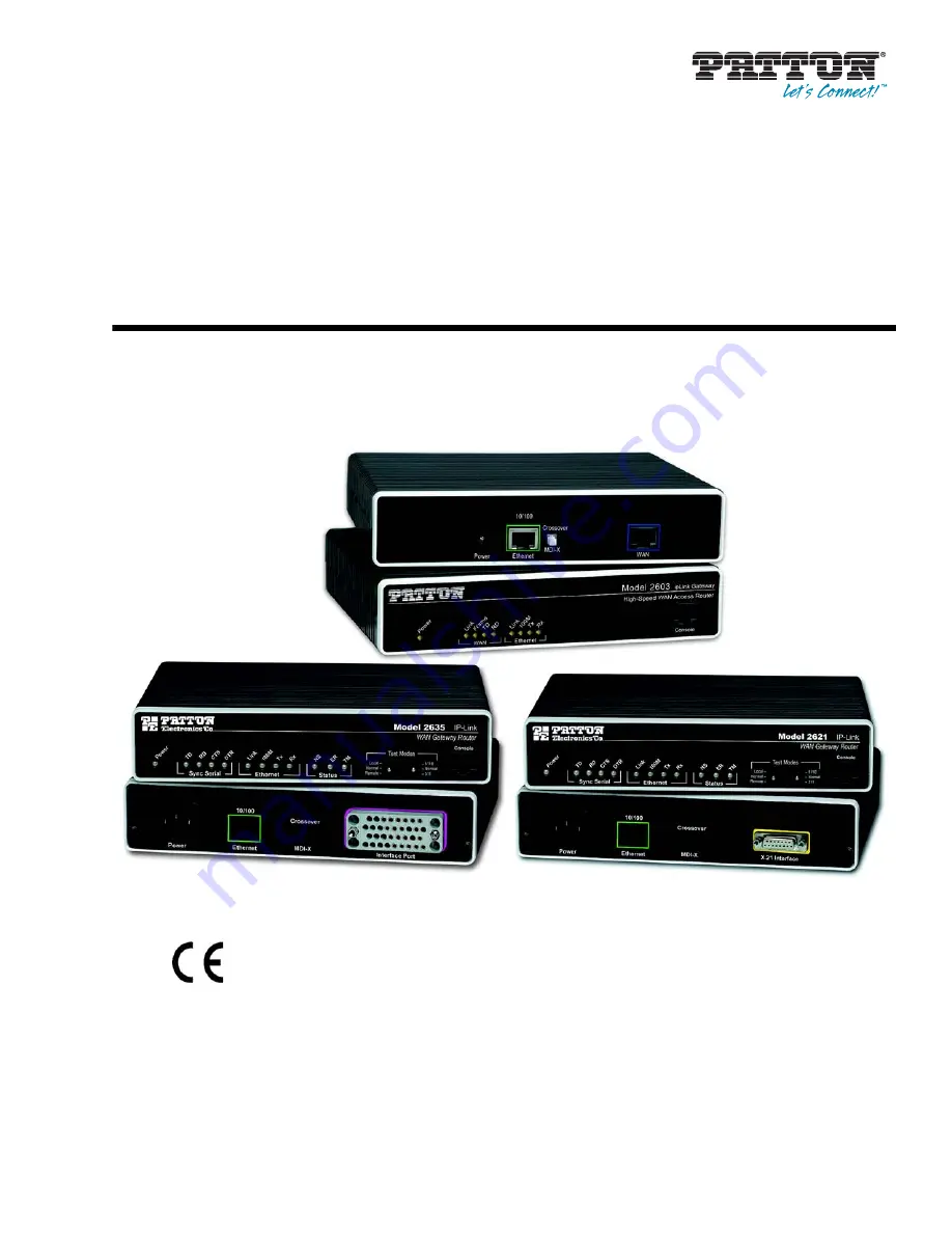
Models 2603, 2621, and 2635

OnSite Series High Speed Routers

User Manual

Sales Office:


+1 (301) 975-1000

Technical Support:


+1 (301) 975-1007

E-mail:


[email protected]

WWW:


www.patton.com

Document Number: 

03328U1-001 Rev. C 

Part Number: 

07M2600Ser-GS

Important


This is a Class A device and is intended for use in a light industrial environment. It is not intended nor approved for use in an industrial 
or residential environment.


Summary of Contents for ONSITE 2603

Page 1: ...al Support 1 301 975 1007 E mail support patton com WWW www patton com Document Number 03328U1 001 Rev C Part Number 07M2600Ser GS Important This is a Class A device and is intended for use in a light industrial environment It is not intended nor approved for use in an industrial or residential environment ...

Page 2: ...should it fail within one year from the first date of the shipment This warranty is limited to defects in workmanship or materials and does not cover customer damage abuse or unauthorized modification If the product fails to perform as warranted your sole recourse shall be repair or replacement as described above Under no condition shall Patton Electronics be liable for any damages incurred by the...

Page 3: ... 6 WAN Services 50 7 Security 68 8 DHCP and DNS Configuration 82 9 IP Services 93 10 System Configuration 96 11 SNTP Client Configuration 104 12 System Status 108 13 Contacting Patton for assistance 112 A Compliance information 115 B Specifications 118 C Cable Recommendations 122 D OnSite Physical Connectors 124 E Command Line Interface CLI Operation 129 ...

Page 4: ...et 19 Protocol support 19 PPP Support 19 WAN Interfaces 19 Management 19 Security 20 Front Panel Status LEDs and Console Port 20 Console port 21 Rear panel connectors and switches 21 Power connector 22 AC universal power supply 22 48 VDC power supply 22 Ethernet port outlined in green 22 MDI X 22 2 Product Overview 24 Introduction 25 Applications Overview 26 3 Initial Configuration 27 Hardware ins...

Page 5: ...ite Series 2603 for T1 Operation 47 Web Configuration 47 Configuring the OnSite Series 2603 for E1 Operation 48 Web Configuration 48 6 WAN Services 50 WAN Services 51 Configuring the OnSite Series 2603 for E1 Operation 51 Web Configuration 51 WAN Service Configuration 52 PPP Configuration 52 PPP Bridged 52 PPP Bridged Remote Site Configuration 52 Central Site Configuration 53 PPP Routed 54 Remote ...

Page 6: ...d DNS Configuration 82 Introduction 83 Services and features normally associated with each other 83 DHCP Server 84 Parameters for the DHCP Server subnet 86 IP Addresses to be available on this subnet 87 DNS server option information 88 Default gateway option information 89 Additional option information 89 DHCP Relay 89 Configuration of the DHCP Relay 89 DNS Relay 91 Configuring the DNS Relay 91 9 ...

Page 7: ...ntacting Patton for assistance 112 Introduction 113 Contact information 113 Patton support headquarters in the USA 113 Alternate Patton support for Europe Middle East and Africa EMEA 113 Warranty Service and Returned Merchandise Authorizations RMAs 113 Warranty coverage 113 Out of warranty service 114 Returns for credit 114 Return for credit policy 114 RMA numbers 114 Shipping instructions 114 A C...

Page 8: ...al Connectors 124 RJ 45 shielded 10 100 Ethernet port 125 RJ 45 non shielded RS 232 console port EIA 561 125 Serial port 126 V 35 M 34 and DB 25 Connector 126 X 21 DB 15 Connector 127 E1 T1 RJ 48C Connector 128 E Command Line Interface CLI Operation 129 Introduction 130 CLI Terminology 130 Local VT 100 emulation 130 Remote Telnet 130 Using the Console 130 Administering user accounts 132 Adding new...

Page 9: ...Contents Models 2603 2621 and 2635 User Manual 9 ...

Page 10: ...ort attributes 42 20 Configurable Ethernet parameters 43 21 Model 2621 X 21 serial port configuration parameters 46 22 Model 2635 V 35 serial port configuration parameters 46 23 Model 2603 T1 E1 WAN port configuration parameters 47 24 T1 configuration 47 25 E1 port configuration 48 26 E1 port configuration 51 27 PPP Bridged Application 52 28 WAN services options 53 29 PPP Routed Application 54 30 ...

Page 11: ...age 91 65 DNS Relay configuration webpage 92 66 DNS Relay configuration completed 92 67 System Services configuration web page 94 68 Authentication web page showing default superuser 97 69 Creating new user 98 70 Alarm Management web page 98 71 Alarm Alarm Error Log configuration 99 72 Remote Access Telnet access limit 99 73 Updating software 100 74 Save configuration changes in non volatile memor...

Page 12: ...the OnSite 58 4 Features and services matrix 84 5 Standard port numbers for the System Services 95 6 Status LED descriptions 111 7 Ethernet Port MDI X switch in out position 125 8 RS 232 Control Port 125 9 V 35 pinout for M 34 DB 25 connectors 126 10 X 21 Interface Model 2621 127 11 T1 E1 Port 128 ...

Page 13: ...4 describes configuring the serial WAN interfaces Chapter 6 on page 50 describes configuring WAN services Chapter 7 on page 68 describes configuring security for the router Chapter 8 on page 82 describes DHCP and DNS configuration Chapter 9 on page 93 describes configuring IP services Chapter 10 on page 96 describes system configuration Chapter 11 on page 104 describes SNTP client configuration Ch...

Page 14: ...RTANT heading calls attention to important information The alert symbol and CAUTION heading indicate a potential haz ard Strictly follow the instructions to avoid property damage The shock hazard symbol and CAUTION heading indicate a potential electric shock hazard Strictly follow the instructions to avoid property damage caused by electric shock The alert symbol and WARNING heading indicate a pot...

Page 15: ...the device shall be easily accessible and pro tected by a circuit breaker For AC powered units ensure that the power cable used meets all applica ble standards for the country in which it is to be installed and that it is con nected to a wall outlet which has earth ground For units with an external power adapter the adapter shall be a listed Lim ited Power Source Hazardous network voltages are pre...

Page 16: ...tions The procedures described in this manual use the following text conventions Table 1 General conventions Convention Meaning Garamond blue type Indicates a cross reference hyperlink that points to a figure graphic table or sec tion heading Clicking on the hyperlink jumps you to the reference When you have finished reviewing the reference click on the Go to Previous View button in the Adobe Acro...

Page 17: ...utes 18 Ethernet 19 Protocol support 19 PPP Support 19 WAN Interfaces 19 Management 19 Security 20 Front Panel Status LEDs and Console Port 20 Console port 21 Rear panel connectors and switches 21 Power connector 22 AC universal power supply 22 48 VDC power supply 22 Ethernet port outlined in green 22 MDI X 22 ...

Page 18: ...via common WAN services The OnSite routers boast easy installa tion offering Console VT 100 Telnet HTTP and SNMP management options The following sections describes the OnSite series features and capabilities General attributes see section General attributes Ethernet see section Ethernet on page 19 Protocol support see section Protocol support on page 19 PPP support see section PPP Support on page...

Page 19: ...ction NAT RFC 3022 with network address port translation NAPT MultiNat with 1 1 Many 1 Many Many mapping Port IP redirection and mapping Frame Relay with Annex A D LMI RFC 1490 and FRF 12 Fragmentation PPP Support Point to point protocol over HDLC PPPoE RFC 2516 Client for autonomous network connection Eliminates the requirement of installing client software on a local PC and allows sharing of the...

Page 20: ... for console and virtual terminal Sepa rate user selectable passwords for SNMP RO RW strings Access list determining up to 5 hosts networks which are allowed to access management system SNMP HTTP TELNET Logging or SMTP on events POST POST errors PPP DHCP IP Front Panel Status LEDs and Console Port The OnSite routers have all status LEDs and console port on the front panel of the unit and all other...

Page 21: ...idle condition Sync Serial TD Green Green indicates a binary 0 condition off indicates a binary 1 or idle condition RD Green Green indicates a binary 0 condition off indicates a binary 1 or idle condition CTS Green ON indicates the CTS signal from the router is active binary 1 off indicates CTS is binary 0 DTR Green ON indicates the DTR signal from the DTE device attached to the serial port is act...

Page 22: ...ielded RJ 45 10Base T 100Base TX Ethernet port using pins 1 2 3 6 See MDI X switch for hub or transceiver configuration The following table defines conditions that occur when the MDI X switch is in the out position MDI X The MDI X push switch operates as follows When in the default out position the Ethernet circuitry takes on a straight through MDI configuration and functions as a transceiver It w...

Page 23: ...OnSite Series High Speed Routers overview 23 Models 2603 2621 and 2635 User Manual 1 General Information ...

Page 24: ...24 Chapter 2 Product Overview Chapter contents Introduction 25 Applications Overview 26 ...

Page 25: ...ecture is understood Also while configuring The OnSite Series router via a browser using the built in HTTP server is very intuitive an understanding of the architecture is essential when using the command line interface CLI commands The fundamental building blocks comprise a router or bridge interfaces and transports the router and bridge each have interfaces A transport provides the path between ...

Page 26: ...h powerful data routing to make shared Internet connectivity simple and easy With NAT support the OnSite routers offer convenient and economical operation by using a single IP address while the integrated DHCP server automates IP address assignment for connected LAN computers Security is standard with built in firewall and violation alerting features that protect the network from would be intruder...

Page 27: ...ble on the IPLink 2603 s T1 E1 interface port 29 Installing an interface cable on the IPLink 2621 s X 21 interface port 31 Installing an interface cable on the IPLink 2635 s V 35 interface port 33 Installing the AC power cord 34 Installing the Ethernet cable 36 IP address modification 37 Web Operation and Configuration 37 PC Configuration 37 Web Browser 37 ...

Page 28: ...r RJ45 RJ45 straight through cable for connecting to control port included with router PC computer with HyperTerminal or equivalent VT 100 emulation program or an ASCII terminal also called a dumb terminal capable of emulating a VT 100 Interface cable installation An OnSite Series router comes with a T1 E1 WAN V 35 or X 21 interface Refer to the appropriate section to install an interface cable on...

Page 29: ...nes see figure 5 The 2603 K also comes with dual BNC for alternate connection to unbalanced 75 ohm E1 lines see figure 6 on page 30 Figure 4 Rear View of the 2603 T showing location of Ethernet and WAN connectors Figure 5 RJ 48C pinout diagram The interconnecting cables shall be acceptable for external use and shall be rated for the proper application with respect to volt age current anticipated t...

Page 30: ... showing location of Ethernet and WAN connectors The interface cable has been installed go to section Installing the AC power cord on page 34 Cro ssover 10 100 Ethern et W AN MDI X Crossover 10 100 Ethernet WAN Power Power MDI X RX connector BNC RX TX RX TX TX connector BNC WAN connector RJ 48C Ethernet connector RJ 45 ...

Page 31: ...fault or as a DCE via internal configuration jumper Figure 7 Rear view of the 2621 showing location of Ethernet and X 21 connectors The interconnecting cables shall be acceptable for external use and shall be rated for the proper application with respect to volt age current anticipated temperature flammability and mechanical serviceability CAUTION Crossover 10 100 Ethernet Power X 21 Interface MDI...

Page 32: ...rewdriver 2 Locate the small daughter board on the Model 2621 board to the right of the DB 9 connector figure 9 shows location of DTE DCE daughter board Figure 9 Location of DTE DCE board 3 The DTE DCE daughter board is installed at the factory with the DTE label and arrows pointing towards the X 21 connector DTE configuration To change to DCE configuration lift the daughter board from the connect...

Page 33: ... when using the Patton cable with the 2635 the V 35 interface at the M 34 end of the cable is a DTE see figure 11 In other words the Patton DB 25 to M 34 cable is a sync null modem cable Figure 10 Rear view of the 2635 showing location of Ethernet and V 35 connectors The interconnecting cables shall be acceptable for external use and shall be rated for the proper application with respect to volt a...

Page 34: ...nstalling the AC power cord The OnSite router comes with an internal or external power supply This section describes installing the power cord into the OnSite router Do the following Note Do not connect the other end of the power cord to the power outlet at this time 1 If your unit is equipped with an internal power supply go to step 2 Otherwise insert the barrel type con nector end of the AC powe...

Page 35: ... 112 to find out how to replace it with a compatible power cord 4 Connect the male end of the power cord to an appropriate power outlet 5 Verify that the green Power LED is lit see figure 13 6 Unplug the AC power cord from the OnSite Series router to power down the unit The OnSite router power supply automatically adjusts to accept an input voltage from 100 to 240 VAC 50 60 Hz Verify that the prop...

Page 36: ...o parity 4 Plug the AC power cord into The OnSite Series router to power up the router 5 Type superuser for Login and press Enter 6 Then type superuser for the password press Enter The interconnecting cables shall be acceptable for external use and shall be rated for the proper application with respect to volt age current anticipated temperature flammability and mechanical serviceability Link Fram...

Page 37: ...abled eth0 fi ip set interface ip1 ipaddress 10 10 19 10 255 255 0 0 enter Sets the new IP address which you have selected The IP address in this example is for illustrative purposes only fi ip list interfaces enter To see if the change in IP address is correct fi system config save enter To save the new IP address in flash memory fi The IP address has now been successfully changed Web Operation a...

Page 38: ...er the OnSite router s IP address into the URL or Address field of the browser To see the OnSite Series router home page refer to the following Figures Model 2603 is shown in figure 14 Model 2621 in figure 15 Model 2635 in figure 16 Figure 14 Model 2603 home page Figure 15 Model 2621 home page ...

Page 39: ...Hardware installation 39 Models 2603 2621 and 2635 User Manual 3 Initial Configuration Figure 16 Model 2635 home page ...

Page 40: ...40 Chapter 4 Ethernet LAN Port Chapter contents Introduction 41 LAN Connections 41 Ethernet Port 41 ...

Page 41: ... to Services Configura tion in the Configuration Menu LAN Change default LAN port IP address button on the main window See figure 17 The primary IP address and mask can be modified here but if you do you will no longer be able to access the OnSite s webpages with the previous IP address The interface associated with the Ethernet is named ip1 You can also configure a secondary IP address to the Eth...

Page 42: ...tes See figure 19 Figure 19 Advanced Ethernet port attributes The three configurable parameters are all either true or false Auto Negotiation the autonegotiation can be enabled default or disabled In some instances autonegotia tion may be problematic if another device on the LAN does not work properly with autonegotiation 100Base Mode the default is for 100BaseT true To configure it for 10BaseT op...

Page 43: ...rt Full Duplex Mode the default value is true for Full Duplex operation Setting it to false configures the Ethernet port to operate only in half duplex mode Rarely do these parameters require a change from their default operation Figure 20 Configurable Ethernet parameters ...

Page 44: ...ort Configuration 45 Serial Interface 45 Variables 45 Web Interface Configuration 46 T1 E1 Interface Configuration 46 Configuring the IPLink Series 2603 for T1 Operation 47 Web Configuration 47 Configuring the IPLink Series 2603 for E1 Operation 48 Web Configuration 48 ...

Page 45: ...RX Clock Invert TX Clock Invert Inverted The clock invert functions could be used to invert the clocks that are used on the serial interface It is not recommended to change this parameter unless requested by Patton Electron ics technical support Keep at default Normal Serial Speed Any n x 64 kbps speed Speed should be enter ed as the rate i e 512 for 512 kbps or 2048 for 2 048 Mbps Defines the gen...

Page 46: ...ers Figure 22 Model 2635 V 35 serial port configuration parameters After the serial port has been configured go to WAN Service Configuration on page 52 section WAN Ser vice Configuration on page 52 for router bridge and WAN service configuration T1 E1 Interface Configuration The OnSite Series Model 2603 is equipped with a user selectable T1 E1 interface The T1 interface is pre sented on an RJ 48C ...

Page 47: ... port configuration parameters Configuring the OnSite Series 2603 for T1 Operation Web Configuration Launch Netscape Internet Explorer or similar web browser type the IP address of the 2603 enter username superuser and password superuser From the main page click on the T1 E1 Configuration See figure 24 Figure 24 T1 configuration ...

Page 48: ...herwise by your service provider Idle code Enabled Disabled When enabled the 2603 inserts idle codes 7E hex on unused timeslots Set this option to Disabled unless instructed otherwise Power Down Normal Powered Down When powered down T1 E1 transceiver input and output lines will be set to high impedance to protect the device set unit to Normal for regular operation After all options have been selec...

Page 49: ...ion therefore select Fdl none for E1 applications Clocking Mode Options are Internal or Receive Recover Clock network In most applications clocking for the 2603 will be derived from the E1 network set the unit for Receive Recover unless instructed otherwise by your service provider Idle code Options are Enabled or Disabled When idle code is Enabled the 2603 inserts idle codes 7E hex on unused time...

Page 50: ...ral Site Configuration 53 PPP Routed 54 Remote site configuration 54 Central Site Configuration 57 LMI Management Frame Relay links 58 LMI Configuration 58 Frame Relay Local Management Interface 58 LMI Configuration Options 59 Web Configuration Methods 59 Frame Relay Configuration 60 Frame Relay bridged 61 Remote Site Configuration 61 Central site configuration 62 Frame Relay Routed 63 Remote Site...

Page 51: ... E1 G 703 G 704 Consult with your service provider which option is required Line Code Choose from AMI or HDB3 Most E1 applications use HDB3 Line Build Out Select 120 Ohms if the E1 connection is made via the RJ 48C connector select 75 Ohm if the E1 connection is made via the dual BNC connectors FDL Mode FDL is a T1 application therefore select Fdl none for E1 applications Clocking Mode Options are...

Page 52: ...office and connects to a router or bridge at a ser vice provider location this can be another OnSite router This application shows configuration for two OnSite units in bridged mode If using a third party router at the Central side review the router s configura tion for connection to a remote bridge See figure 27 Figure 27 PPP Bridged Application IPlink series Remote First configure the IP address...

Page 53: ...N service Verify the settings to be Interface 1 LLC header mode dialout LLC header mode off HDLC header mode on No authentication Leave User name and Password blank Click on Create Central Site Configuration If the central site also has an OnSite you may configure as described in this sec tion Refer to the web page images for the Remote OnSite configuration above In this example the IP address of ...

Page 54: ...Routed This application shows configuration for two OnSite units in PPP routed mode An OnSite may be used as the router at the Central site but it is not necessary You can use a third party router as long as it supports PPP routed operation If using a third party router at the Central site review the router s configuration See figure 29 Remote site configuration First configure the IP address on t...

Page 55: ...n this example it is called PPP Routed Description PPP Routed Interface 1 WAN IP address 192 168 164 2 255 255 255 255 LLC Header Mode off HDLC Header Mode ON No authentication Username blank Password blank Figure 30 PPP Routed Configuration menu 4 Click on Create 5 Go to Services Configuration WAN Edit for PPP routed Edit IP Interface Ipaddr enter the WAN IP Address and Mask in this example 192 1...

Page 56: ...is example enter 192 168 164 3 in the Gateway field See figure 32 8 Click the Update button Figure 32 Configuring the gateway The other fields should be Destination 0 0 0 0 Gateway 192 168 164 3 Mask 0 0 0 0 Cost 1 Interface blank You can see the status of the PPP link by going to the Edit PPP web page and paging down until you see the Summary description In figure 33 the PPP link is in the Establ...

Page 57: ...cess the configuration web pages In this example the PC s IP address is 192 168 172 229 24 Notice that this subnet differs from the subnets of the WAN service link and also the Ethernet port of the remote OnSite which we just configured 1 Bring up the web page management system on your browser by entering the IP address of the IPlink 192 168 172 3 2 On the Menu go to Service Configuration then to ...

Page 58: ...ption To get to the Edit PPP web page follow this path Services Configuration WAN Edit Edit PPP LMI Management Frame Relay links LMI Configuration Frame Relay Local Management Interface The Frame Relay Local Management Interface LMI is a mech anism that two separate frame relay systems can use to communicate the status of the interface The LMI inter face allows dynamic updates on the status of the...

Page 59: ...T1 617 protocol will be used The unit will operate as both the Network and User side of the connection Management State Defines the current state of the DTE side LMI Possible options are as follows Mgt_Port_DOWN Currently the LMI on the DTE side is DOWN Mgt_Port_UP Currently the LMI on the DTE side is UP Management Auto Start Default Value FALSE The management Auto Start variable allows the user t...

Page 60: ...ay service can be configured for either bridged or routed applications The use of DLCI values since the original publication of the Frame Relay specifications has been modified as to their use For the two octet address format they are as follows DLCI Number Use 0 Used for in channel signaling 1 15 Reserved DLCI s 16 991 Assigned using Frame Relay connection procedures Verify that none of these val...

Page 61: ...n to WAN Delete the factory default WAN services already defined 3 Click on Create a new service in the main window select Frame Relay bridged and click on Continue 4 Enter the description for the circuit in the Description field This is a mandatory field Without a descrip tion you cannot create a WAN service 5 Click on Create a new service in the main window select Frame relay bridged and click o...

Page 62: ...r routed applications the port should be set to frf for bridged applications the port should be set to fr Click on the Create button Figure 36 Frame Relay Channel configuration Central site configuration Note If you are using a OnSite at the Central location follow the instructions below otherwise refer to your third party router documentation for configu ration See the web pages for the OnSite ab...

Page 63: ... 12 Frame Relay Fragmentation will be disabled if set to any other value it will set the fragmentation size used Port Defines the port that should be used to setup the Frame Relay Connection For routed applications the port should be set to frf for bridged applications the port should be set to fr Click on the Create button This conclude the central site configuration Frame Relay Routed This appli...

Page 64: ... Consult with your service provider for the DLCI number required Encapsulation Method Defines the RFC1490 encapsulation type that will be used by the channel Choose the encapsulation method best suited for your network needs from the following options Routed IP default value Raw WAN IP address Enter the IP address assigned to the WAN port V 35 X 21 or T1 E1 Enable NAT on this interface In this exa...

Page 65: ...in this example it is the default 8192 Channel segment size The channel segment size is used to define fragmentation of the packets based on the Frame Relay Forum IA FRF 12 If this variable is set to 0 then FRF 12 Frame Relay Fragmentation will be disabled if set to any other value it will set the fragmentation size used Port Defines the port that should be used to setup the Frame Relay Connection...

Page 66: ...t for configuring the OnSite via the web pages 1 Bring up the web page management system on your browser by entering the IP address of the OnSite 2 On the Menu go to Services Configuration then to WAN Delete the factory default WAN services already defined 3 Click on Create a new service in the main window select Frame Relay routed and click on Continue 4 Enter the description for the circuit in t...

Page 67: ...PDU Enter the number of transmit side max PDU in this example it is the default 8192 Channel segment size The channel segment size is used to define fragmentation of the packets based on the Frame Relay Forum IA FRF 12 If this variable is set to 0 then FRF 12 Frame Relay Fragmentation will be disabled if set to any other value it will set the fragmentation size used Port Defines the port that shou...

Page 68: ...onfiguring the security interfaces 71 Configuring Security Policies 73 Deleting a security Policy 74 Enabling the Firewall 74 Firewall Portfilters 74 Security Triggers 75 Intrusion Detection System IDS 78 Introduction to NAT 80 Enabling NAT 80 Global address pool and reserved map 80 ...

Page 69: ...ough This is a significant security risk This risk can be avoided by using security triggers Triggers tell the security mechanism to expect these second ary sessions and how to handle them Rather than allowing a range of port numbers triggers handle the situa tion dynamically opening the secondary sessions only when appropriate The triggers work without needing to understand the application protoc...

Page 70: ...fields as follows and click on the Create button See figure 42 Ipaddr 192 168 101 1 Mask 255 255 255 0 Figure 42 IP address of PPP routed WAN service The next step in configuring the router is to add the default gateway route The WAN IP address of the routed PPP WAN service at the CO site is 192 168 101 2 so this will be the gateway IP address on the OnSite 1 Click on IP routes under Services Conf...

Page 71: ...of the WAN service and the gateway are properly configured See figure 43 Figure 43 Valid gateway route Configuring the security interfaces The interfaces and routes have been configured on the OnSite Router The Ethernet side of the OnSite router will be configured to be an internal interface and the WAN side is selected to be the external interface since it is on public side of the modem connectio...

Page 72: ... on the hyperlink Add interface 3 Select ip1 beside the Name pull down menu and select internal beside the Interface Type pull down menu Click on Create See figure 45 Figure 45 Define ip1 interface as Internal 4 Again click on the hyperlink Add interface to define the WAN interface as external 5 Select ppp 0 beside the Name pull down menu and select external beside the Interface Type pull down men...

Page 73: ...e external and internal interfaces 1 Go to the last section on the Security Interface Configuration webpage called Policies Triggers and Intru sion Detection Click on the hyperlink Security Policy Configuration See figure 47 Figure 47 Security Policy Configuration hyperlink 2 Click on the hyperlink New Policy See figure 48 Figure 48 New Policy link to configuration webpage 3 Select the parameters ...

Page 74: ...r Security Click on Change State 3 Next select Enabled for Firewall Click on Change State The network is now secure All the interfaces which have been defined are protected and all traffic is blocked between different the different interface types That is all traffic is blocked between the external and internal interfaces The next section describes how to configure the Firewall for allowing certai...

Page 75: ...tween the two networks Security Triggers Security triggers are used to allow an application to open a secondary port in order to transport data The most common example is FTP This procedure sets up a trigger on the Firewall to permit an FTP session from PC A to PC B but not the reverse 1 First create an outbound only portfilter for FTP and add it to the item0 policy 2 Following the path given in s...

Page 76: ...e portfilter allows an ftp control channel but does not allow the use of a secondary data channel for passing data by ftp To enable the FTP data channel add a trigger to open a secondary channel only when data is being passed This minimizes the number of open ports Each open port is a security risk 1 From the Configuration Menu Configuration Security Security Trigger Configuration New Trig ger 2 S...

Page 77: ...Security Triggers 77 Models 2603 2621 and 2635 User Manual 7 Security Figure 52 Adding trigger for FTP data transfer You should now be able to use FTP commands to pass data between Remote and Local ...

Page 78: ... allows an attacker to create a shadow copy of the world wide web WWW All access to the shadow Web goes through the attacker s machine so the attacker can monitor all of the victim s activities and send false data to or from the victim s machine When enabled packets destined for the victim host of a spook ing style attack are blocked Victim Protection Block Duration Default 600 seconds DOS Attack ...

Page 79: ...ged SYN ACK packets Once the queue is full the system will ignore all incoming SYN request and no legitimate TCP connections can be established Once the maximum number of unfinished TCP handshaking sessions is reached an attempted DOS attack is detected The firewall blocks the suspected attacker for the time limit specified in the DOS Attack Block Duration parameter Maximum Ping Count Default 15 S...

Page 80: ... insides hosts can share the same global address Setting the protocol number to 255 0xFF means that the mapping will apply to all protocols Setting the port number to 65535 0xFFFF for TCP or UDP protocols means that the mapping will apply to all port numbers for that protocol Some applications embed address and or port information in the payload of the packet The most notorious of these is FTP For...

Page 81: ...n this example 10 10 19 11 5 Click on the hyperlink Add Reserved Mapping 6 Set the parameters to the following values See figure 54 Global IP Address 100 100 100 101 Internal IP address 10 10 19 11 Transport Type all Port Number 65535 This port number means all port numbers for TCP or UDP protocols will be mapped 7 Click on Add Reserved Mapping Figure 54 NAT Reserved mapping configuration The PC o...

Page 82: ...with each other 83 DHCP Server 84 Parameters for the DHCP Server subnet 86 IP Addresses to be available on this subnet 87 DNS server option information 88 Default gateway option information 89 Additional option information 89 DHCP Relay 89 Configuration of the DHCP Relay 89 DNS Relay 91 Configuring the DNS Relay 91 ...

Page 83: ...client s point of view The relay operates by forwarding all broadcast client request to known DHCP servers The DHCP relay listens on all available interfaces All relay server communi cation is unicast It is important that valid routes are set up to the server and also to the client Services and features normally associated with each other The following table figure 4 is to give guidance on what se...

Page 84: ...outed 3 When DHCP Relay is used with a Bridged WAN service the DHCP server must be on the same subnet as the clients and the OnSite DHCP Server Go to the DHCP Server webpage from the Configuration Menu Services Configuration DHCP Server The DHCP server default is disabled Click on the Enable button to begin the configuration process Table 4 Features and services matrix The feature in this column w...

Page 85: ...or this subnet defines the subnet and netmask the origin of the subnet maximum lease time and default lease time IP addresses to be available on this subnet either define the IP address range for the DHCP server IP pool or use the default range which is a set of 20 IP addresses DNS server option information enter the IP addresses of the primary and secondary DNS servers which are provided to the D...

Page 86: ...t Four parameters are in the section for defining the DHCP subnet See figure 57 Figure 57 DHCP Server subnet parameters The first two parameters are applicable when you will define the subnet Subnet value It is necessary to enter the selected value here and the Subnet mask if you do not Get subnet from IP interface See description for the 3rd parameter Subnet mask ...

Page 87: ...lt value is 86 400 seconds Default lease time the default value is 43 200 seconds IP Addresses to be available on this subnet The next section see figure 58 has three parameters Figure 58 DHCP IP address pool Start of address range Enter the first IP address to be available in the DHCP IP address pool End of address range Enter the last IP address to be available in the DHCP IP address pool Use a ...

Page 88: ...he DNS server IP addresses Enter the IP addresses of the primary and secondary DNS servers Subsequently the client will receive these addresses when assigned an IP address When the client makes a DNS inquiry it sends the request directly to the appropriate DNS server The OnSite router merely forwards the packet The third parameter is Use local host address as DNS server which is the IP address of ...

Page 89: ...SMTP server POP3 server NNTP server WINS server Time servers Refer to figure 61 as an example of multiple options to be sent to the clients Figure 61 DHCP server optional information example DHCP Relay With this webpage you can enter a list of IP addresses for DHCP servers When a client requests an IP address it uses one of the DHCP addresses listed in the DHCP relay webpage The OnSite forwards or...

Page 90: ...he DHCP Relay webpage enter the IP address of a DHCP server and click on the Cre ate button See figure 63 The IP addresses will appear in the section section Edit DHCP server list In the second section you may update or delete the DHCP server IP addresses See figure 63 To update or change a DHCP server IP address enter the desired IP address over the IP address which is no longer valid Click on th...

Page 91: ...S server responses to the client You can configure the DNS Relay for two IP addresses These are for access to primary and secondary DNS servers Configuring the DNS Relay Go to the DNS Relay webpage by following the hyperlink path Configuration Menu Services Configura tion DNS Relay See figure 64 Figure 64 Hyperlink path to the DNS Relay webpage Enter the IP address of the primary DNS server see fi...

Page 92: ... webpage You can change the IP address of the DNS servers on the DNS Relay webpage see figure 66 by modifying the IP address requiring the change and clicking on the Update button To delete the IP address of a DNS server check the Delete box then click on the Update button Figure 66 DNS Relay configuration completed ...

Page 93: ...93 Chapter 9 IP Services Chapter contents IP Services 94 WEB Server 94 CLI Configuration 94 Associated Ports for the different System IP Services 95 ...

Page 94: ...must be wisely disabled is the WEB Server After you disable the WEB Server from the web page you can no longer access the any of the OnSite s web pages The only way to enable it is through the Command Line Interface CLI CLI Configuration After configuring a terminal emulator to access the OnSite s serial port there are two commands for the enabling or disabling the WEB Server The following command...

Page 95: ...P Services This section is for information purposes only Consult the table to identify which ports are associated with the different System IP Services Table 5 Standard port numbers for the System Services System IP Service TCP UDP FTP 21 control con nection 20 data con nection TFTP 69 SNMP 161 WEB Server 80 80 ...

Page 96: ...System Configuration Chapter contents Introduction 97 Authentication 97 Alarm 98 Remote Access 99 Update 100 Save 100 Backup Restore 100 Restart 101 Website Settings 101 Error Log 102 SNMP Daemon 102 System Tools 103 ...

Page 97: ...ite or to restore the OnSite to factory defaults Key the key version is used to identify which features are installed in the OnSite Website Settings configures the refresh rate of the web pages Error Log displays the Syslog Settings and shows recent configuration errors from the OnSite SNMP Daemon to modify the SNMP parameters for the OnSite Tools provides ping and traceroute commands from the OnS...

Page 98: ...Figure 69 Creating new user Alarm Access the configuration and status of the alarms Figure 70 Alarm Management web page All OnSites have the PP over Threshold and NP over Threshold alarms The Model 2603 has additional alarms for the T1 E1 WAN port An alarm can be tested by clicking on the Generate button Similarly by clicking on the Clear button the alarm is cleared that is turned off however the ...

Page 99: ...o configure the Alarm Error Log click on Modify Alarms to reach the webpage See figure 71 Figure 71 Alarm Alarm Error Log configuration The Alarm Error Log can be enabled or disabled The severity level of the Alarm Log can also be configured Similarly each alarm can be set for its own severity level Remote Access The OnSite can be accessed via Telnet known as Remote Access The length of access ove...

Page 100: ...e configuration changes to non volatile memory it is essential to click on the Save button on this webpage See figure 74 If you do not do this all configuration changes are stored only in volatile memory meaning that if the OnSite is restarted all configuration changes are lost Click on the Save button and wait until seeing the message Saved information model to im conf Figure 74 Save configuratio...

Page 101: ... factory default settings see figure 76 Then click on the Restart button No warning is given before beginning the reboot process You will need to configure the IP address of the Ethernet port again as described in Chapter 3 Initial Configuration Figure 76 Restoring to factory defaults Website Settings The refresh rate of the webpages is a configurable parameter Enter the desired refresh rate in se...

Page 102: ...SNMP Daemon For remote management from an SNMP capable management station the OnSite s SNMP Daemon must be configured To identify a specific OnSite configure the Static Variables which the system administrator may use for link identification The Community Table has three configurable parameters Password this is the password which the remote management station must use to access the OnSite for read...

Page 103: ... of the SNMP trap along with its password System Tools The System Tools webpage provides two utilities for testing network connectivity The two utilities are ping and traceroute Enter the IP address of the device to ping or traceroute and click on the appropriate button The example in shows a successful ping of a PC Figure 80 Ping and Traceroute utilities ...

Page 104: ...11 SNTP Client Configuration Chapter contents Introduction 105 Configuring the SNTP Client 105 SNTP Client Mode Configuration Parameters 105 SNTP Client General Configuration Parameters 106 System Clock Setting 106 ...

Page 105: ... a multipoint to point mode Broadcast mode is for use when the SNTP server is on the local network that is the same subnet as the OnSite When Unicast mode is enabled the OnSite sends a request to the server designated in the field containing the SNTP server s IP address See figure 81 This is a point to point communication link The OnSite requests from one server The server sends the timing informa...

Page 106: ...e is 5 seconds Packet retries When no response after the timeout period is received from the SNTP server the OnSite will send another request for the number times configured in this parameter The maximum number of retries is 10 Default value is 2 Polling value in minutes The SNTP client will automatically send a time synchronization request period ically If set to zero 0 the polling mechanism is d...

Page 107: ...t Configuration Figure 83 Configuration of the internal system calendar clock After entering the system clock values click on the Set Clock button to save in volatile memory If the OnSite is rebooted either soft or by power cycling the Clock Setting returns to its default value ...

Page 108: ...108 Chapter 12 System Status Chapter contents System Status 109 Port Connection Status 109 LAN Status 110 WAN Status 110 Hardware Status 110 Defined Interfaces 110 Status LEDs 111 ...

Page 109: ... web pages WAN Status parameters and links to the WAN services defined on the serial port PPPoE Status the connection authentication status is available when the PPPoE WAN service is configured and activated Hardware Status shows the time that the OnSite has been operating the current time software version and a link to configure the time including the SNTP client Defined Interfaces provides links...

Page 110: ...IP address of the WAN service is statically assigned or as a DHCP client Default gateway the gateway defined by the IP Routes submenu item under Services Configuration in the Configuration Menu Primary DNS DNS client is currently not available Hardware Status The definitions of the parameters are as follows Up Time this is the time since the OnSite was last rebooted either soft or hard power cycle...

Page 111: ...on RD Green Green indicates a binary 0 condition off indicates a binary 1 or idle condition Sync Serial TD Green Green indicates a binary 0 condition off indicates a binary 1 or idle condition RD Green Green indicates a binary 0 condition off indicates a binary 1 or idle condition CTS Green ON indicates the CTS signal from the router is active binary 1 off indicates CTS is binary 0 DTR Green ON in...

Page 112: ... support headquarters in the USA 113 Alternate Patton support for Europe Middle East and Africa EMEA 113 Warranty Service and Returned Merchandise Authorizations RMAs 113 Warranty coverage 113 Out of warranty service 114 Returns for credit 114 Return for credit policy 114 RMA numbers 114 Shipping instructions 114 ...

Page 113: ...5 1007 Fax 1 253 663 5693 Alternate Patton support for Europe Middle East and Africa EMEA Online support available at http www patton inalp com E mail support email sent to support patton inalp com will be answered within 1 day Telephone support standard telephone support is available five days a week from 8 00 am to 5 00 pm CET 0900 to 1800 UTC GMT by calling 41 0 31 985 25 55 Fax 41 0 31 985 25 ...

Page 114: ...t will be issued upon receipt and inspection of the equipment 30 to 60 days We will add a 20 restocking charge crediting your account with 80 of the purchase price Over 60 days Products will be accepted for repairs only RMA numbers RMA numbers are required for all product returns You can obtain an RMA by doing one of the following Completing a request on the RMA Request page in the Support section...

Page 115: ...ix A Compliance information Chapter contents Compliance 116 EMC 116 Safety 116 PSTN Regulatory 116 Radio and TV Interference FCC Part 15 116 CE Declaration of Conformity 116 Authorized European Representative 117 ...

Page 116: ...hat inter ference will not occur in a particular installation If the equipment causes interference to radio or television reception which can be determined by disconnecting the cables try to correct the interference by one or more of the following measures moving the computing equipment away from the receiver re orienting the receiving antenna and or plugging the receiving equipment into a differe...

Page 117: ...n Representative 117 Models 2603 2621 and 2635 User Manual A Compliance information Authorized European Representative D R M Green European Compliance Services Limited Avalon House Marcham Road Abingdon Oxon OX14 1UD UK ...

Page 118: ... Characteristics 119 Ethernet 119 Sync Serial Interface 119 T1 E1 Interface 119 Protocol Support 120 PPP Support 120 Management 120 Security 121 Dimensions 121 Power and Power Supply Specifications 121 AC universal power supply 121 48 VDC power supply 121 ...

Page 119: ...ry Front panel LEDs indicate Power WAN Ethernet LAN speed and status Field Factory Default Option Standard 1 year warranty Ethernet Auto sensing Full Duplex 10Base T 100Base TX Ethernet Standard RJ 45 and built in MDI X cross over switch IEEE 8021 d transparent learning bridge up to 1 024 addresses 8 IP address subnets on Ethernet interface Sync Serial Interface ITU T X 21 or V 35 interface Availa...

Page 120: ...grated Application Level Gateway with support for over 80 applications NAT MultiNat with 1 1 mapping NAT Many 1 NAT Many Many mapping NAT Port IP redirection and mapping IGMPv2 Proxy support RFC 2236 Frame Relay with Annex A D LMI RFC 1490 and FRF 12 Fragmentation PPP Support Point to Point Protocol over HDLC PPPoE RFC 2516 Client for autonomous network connection Eliminates the requirement of ins...

Page 121: ...TELNET Logging or SMTP on events POST POST errors PPP DHCP IP Dimensions 1 58H x 4 16W x 3 75D in 10 6H x 4 1W x 8 8D cm Power and Power Supply Specifications The OnSite router may come with either an AC or DC power supply AC universal power supply The OnSite Series router offers internal or external AC power supply options The internal power supply connects to an AC source via an IEC 320 connecto...

Page 122: ...122 Appendix C Cable Recommendations Chapter contents Ethernet Cable 123 Adapter 123 ...

Page 123: ...port EIA 561 on page 125 The interconnecting cables shall be acceptable for external use and shall be rated for the proper application with respect to volt age current anticipated temperature flammability and mechanical serviceability The interconnecting cables shall be acceptable for external use and shall be rated for the proper application with respect to volt age current anticipated temperatur...

Page 124: ...sical Connectors Chapter contents RJ 45 shielded 10 100 Ethernet port 125 RJ 45 non shielded RS 232 console port EIA 561 125 Serial port 126 V 35 M 34 and DB 25 Connector 126 X 21 DB 15 Connector 127 E1 T1 RJ 48C Connector 128 ...

Page 125: ...t EIA 561 The RS 232 serial control port of the OnSite is configured to operate as a DCE Table 7 Ethernet Port MDI X switch in out position Pin No Signal Name Direction 1 TX from OnSite 2 TX from OnSite 3 RX to OnSite 4 5 6 RX to OnSite 7 8 Table 8 RS 232 Control Port Pin No Signal Name Direction 1 DSR from OnSite 2 CD from OnSite 3 DTR to OnSite 4 Signal Ground 5 RD from OnSite 6 TD to OnSite 7 C...

Page 126: ...or M 34 DB 25 connectors M 34 Pin No DB 25 Pin No Signal Name Direction A 1 Frame Chassis Ground n a P 2 TD a from DTE R 3 RD a to DTE C 4 RTS from DTE D 5 CTS to DTE E 6 DSR to DTE B 7 Signal Ground n a F 8 CD to DTE X 9 RC b to DTE 10 W 11 XTC b from DTE AA 12 TC b to DTE 13 S 14 TD b from DTE Y 15 TC a to DTE T 16 RD b to DTE V 17 RC a to DTE L 18 Local Loopback to DTE 19 H 20 DTR from DTE N 21...

Page 127: ...Signal Ground or Common Return 2 T Transmit Data a from DTE 3 C Control a from DTE 4 R Receive Data a to DTE 5 I Indication a to DTE 6 S Signal Timing a to DTE 7 8 Ga DTE Common Return 9 T Transmit Data a from DTE 10 C Control b from DTE 11 R Receive Data b to DTE 12 I Indication b to DTE 13 S Signal Timing b to DTE 14 15 1 Frame Ground 2 Transmit A 3 Control A 4 Receive A 5 Indication A 6 Signal ...

Page 128: ... T1 E1 transmit signals are not polarity sensitive even though they have the traditional designation of Tip and Ring Figure 86 T1 E1 RJ 48C connector Table 11 T1 E1 Port Pin No Signal 1 Receive Ring 2 Receive Tip 3 Shield Receive 4 Transmit Ring 5 Transmit Tip 6 Shield Transmit 7 8 1 2 3 4 5 6 7 8 RX RX TX TX ...

Page 129: ...s Introduction 130 CLI Terminology 130 Local VT 100 emulation 130 Remote Telnet 130 Using the Console 130 Administering user accounts 132 Adding new users 132 Setting user passwords 132 Changing user settings 133 Controlling login access 133 Controlling user access 133 ...

Page 130: ... an interface Object an object is anything that you can create and manipulate as a single entity for example interfaces transports static routes and NAT rules List Objects are numbered entries in a list For example if you have created more than one ethernet trans port the following command ethernet list transports produces a list of numbered transport objects ID Name Port 1 eth2 ethernet 2 eth1 et...

Page 131: ...space and To continue our example fi ethernet list ports transports fi ethernet list Then fi ethernet list transports fi ethernet list transports enter Ethernet transports ID Name Port 1 eth1 ethernet fi Another example shows when the user must provide a parameter fi ip list clear add delete set attach attachbridge detach show interface ping fi ip interface name The name of the interface In this i...

Page 132: ...me Comment system add login user username Comment The first command creates a user who can access the system via a dialin connection using PPP for example The second command creates a user who can login to the system For example the commands system add user fred user with dialin access system add login joe user with login access creates two new users called fred and joe The accounts are created wi...

Page 133: ...ng user settings To change any of the default settings for a user use the following commands For example to change the set tings for user fred system set user fred access default engineer superuser system set user fred maydialin enabled disabled system set user fred mayconfigure enabled disabled For example to change the security level for fred enter system set user fred access engineer Note Only ...

Reviews: