USER
MANUAL
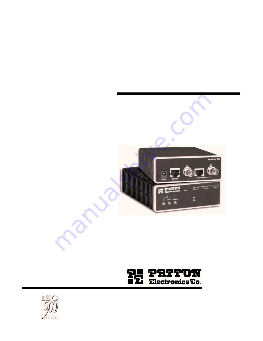
MODEL 2707/I
G.703 NTU with 10Base-T Ethernet Interface
SALES OFFICE(301) 975-1000TECHNICAL SUPPORT(301) 975-1007
Part# 07M2707I-UMDoc# 08625U2-001Rev. CRevised 10/27/06
An ISO-9001
Certified
Company
Page 1: ... MANUAL MODEL 2707 I G 703 NTU with 10Base T Ethernet Interface SALES OFFICE 301 975 1000 TECHNICAL SUPPORT 301 975 1007 Part 07M2707I UM Doc 08625U2 001 Rev C Revised 10 27 06 An ISO 9001 Certified Company ...
Page 2: ...0 ohm to the G 703 Network 14 Connecting the 10Base T Ethernet port to a PC DTE 14 Connecting the 10Base T Ethernet Port to a Hub 15 Power Connection 15 Universal AC Power 100 240 VAC 15 DC Power 16 6 0 Operation 17 6 1 Power up 17 6 2 LED Status Monitors 17 6 3 Operating Line Loopback LL 19 A G 703 Specifications 20 A 1 Network Data Rate 20 A 2 Network Connector 20 A 3 Nominal Impedance 20 A 4 Li...
Page 3: ...3 B 9 Diagnostics 21 B 10 Indicators 21 B 11 Configuration 21 B 12 Power Supply 22 B 13 Humidity 22 B 14 Temperature 22 B 15 Dimensions 22 C Factory Replacement Parts and Accessories 23 ...
Page 4: ...structions may cause interference to radio and television reception The Model 2707 I has been tested and found to comply with the limits for a Class A computing device in accordance with the specifi cations in Subpart B of Part 15 of FCC rules which are designed to pro vide reasonable protection from such interference in a commercial installation However there is no guarantee that interference wil...
Page 5: ... may be obtained from Patton Electronics Technical Services at Tel 1 301 975 1007 Email support patton com URL http www patton com Note Packages received without an RMA number will not be accepted Caution This device is not intended to be connected to the public telephone network ...
Page 6: ... Telecom networks 2 2 DESCRIPTION The Model 2707 I receives clear channel E1 G 703 2 048 Mbps data from the telco s digital data network The Model 2707 I terminates the G 703 telco interface and converts the data for transmission to a user oriented 10Base T 802 3 Ethernet interface The Ethernet Model 2707 I supports an integrated 10Base T 802 3 Ethernet port with transparent bridging capability fo...
Page 7: ...ols Once each of the network layer protocols have been configured datagrams from the established network layer protocol can be sent over the link The link will remain configured for these communications until explicit LCP or NCP packets close the link down or until some external event occurs The PPP Bridging Control Protocol BCP defined in RFC 1638 config ures and enables disables the bridge proto...
Page 8: ...ligence from the 2707 I The associated Cisco configuration will set serial interface s0 to accommodate half bridging for the above example Authentication is optional under PPP In a point to point leased line link incoming customer facilities are usually fixed in nature therefore authen tication is generally not required Some networking systems do not define network numbers in packets sent out over...
Page 9: ...on for a wide range of applications The DIP switch is accessed from the underside Figure 2 shows the location of the DIP switches on the bottom of the printed circuit board Figure 2 Underside of Model 2707 I showing location of DIP switches The DIP switches can be configured as either ON or OFF Figure 3 shows the orientation of the DIP switches with respect to ON OFF posi tions Figure 3 Close up v...
Page 10: ...po lar violation when excessive zeros in the data stream are detected Table 1 Switch S1 settings Switch Description Setting S1 1 Line Coding Off HDB3 On AMI S1 2 Line Loopback toward E1 line Note The Model 2707 I when in line loopback mode will loop the network line and return any trafic received on the E1 line to the sending device at the remote end Off LLB disabled On LLB enabled S1 3 Reserved O...
Page 11: ...no pulse Every other pulse is inverted from the previous pulse in polarity so that the signal can be effectively transmitted This means however that a long sequence of zeros in the data stream will cause problems since the NTU receiving the signal relies on the signal to recover the 2 048 Mbps clock Note If you must use AMI you should ensure that the data terminal equipment connected to the unit p...
Page 12: ...o section Connect ing Dual Coaxial Cable 75 ohm to the G 703 Network on page 13 The 120 ohm RJ 48C jack is used for connecting to a 120 ohm twisted pair G 703 network interface If your G 703 network terminates with a RJ 48C refer to section Connecting the Twisted Pair 120 ohm to the G 703 Network on page 14 The Ethernet 10Base T port is configured as DTE Data Terminal Equipment If the Model 2707 I...
Page 13: ...s JP2 JP5 JP6 and JP7 must be installed over the jumpers The jumpers are located next to the BNC connectors Do the following to configure the jumpers 1 Open the case by inserting a screwdriver into the slots and twist the screwdriver head slightly The top half of the case will separate from the lower half of the case Take caution not to damage any of the PC board mounted components 2 Open the case...
Page 14: ...nect the wires as shown in Figure 7 below and Figure 8 on page 15 Figure 7 Connecting the 10Base T Ethernet Port to a PC NETWORK SIGNAL SIGNAL PIN RX R RX T TX R TX T Shield Shield 4 5 1 2 3 6 TX R TX T RX R RX T Shield Shield 1 2 3 4 5 6 7 8 1 2 3 4 5 6 7 8 RX Receive Ring RX Receive Tip Shield TX Transmit Ring TX Transmit Tip Shield No connection No connection Signal Name RJ 48C Jack 1 TD data o...
Page 15: ... to a hub Power Connection Universal AC Power 100 240 VAC The Model 2707 I uses a 5VDC 2A universal input 100 240VAC power supply center pin is 5V The universal input power supply has a male IEC 320 power entry connector This power supply connects to the Model 2707 I by means of a barrel jack on the rear panel Many international power cords are available for the universal power supply Note The Mod...
Page 16: ...ower connector plugs into the barrel power supply jack on the 2707 I See Figure 10 Figure 10 Connecting DC power to the 2707 I DC power supply To Power Supply Jack To 48VDC Source Vin Vin SWITCHING POWER SUPPLY MODEL SYD1106 0505 INPUT 36 60V 0 2A MAX OUTPUT 5V 1 0A OUTPUT POWER 5W MAX S N G01234567890 MADE IN CHINA BY SUNNY Black lead V Red lead V Barrel power connector ...
Page 17: ...the Model 2707 I please review section Power Connection on page 15 to verify that the unit is properly connected to the appropriate power source 6 2 LED STATUS MONITORS The Model 2707 I features six front panel LEDs that monitor connections on the G 703 and 10Base T links signaling error and test modes Figure 11 shows the front panel location of each LED Table 2 on page 18 lists descriptions of ea...
Page 18: ...e patterns have higher priority buffer saturation has greater priority than an empty MAC table Valid system statuses are 1 pulse system status is okay 2 pulses no MAC entries in the MAC Address Table 3 pulses Clear to Send CTS or Carrier Detect DCD from base unit are not asserted 4 pulses IM1 I buffer is saturated 5 pulses WAN receive frame s too large 6 pulses WAN receive frame s not octet aligne...
Page 19: ... separately on each unit Figure 12 Line loopback for a network termination application To perform an LL test set DIP switch S1 2 to On The TM LED will be lit while the unit is in loopback test mode Model 2707 I Network Clocking Cable Span 2 Mbps G 703 Network G 703 NTU Model 2707 I Clock Data Clock Data Data Ethernet Device ...
Page 20: ...2 048 Mbps A 2 NETWORK CONNECTOR RJ 48C Dual Coax BNC A 3 NOMINAL IMPEDANCE 75 120 ohm A 4 LINE CODING Selectable AMI or HDB3 A 5 LINE FRAMING G 703 Unframed A 6 CLOCKING Internal or Network Receive Recover A 7 DISTANCE Maximum 6 000 ft 1 6 km On 24 AWG cable ...
Page 21: ... B 4 PROTOCOL PPP RFC 1661 with Bridging Control RFC 1638 B 5 MAC ADDRESS TABLE SIZE 4096 entries B 6 MAC ADDRESS AGING MAC addresses deleted after 8 minutes of inactivity B 7 FRAME BUFFER 512 Frames B 8 FRAME LATENCY 1 frame B 9 DIAGNOSTICS Line Loopback B 10 INDICATORS E 1 Link 10Base T Link Ethernet Status Test Mode B 11 CONFIGURATION 8 Position DIP Switch ...
Page 22: ...2 B 12 POWER SUPPLY 5 VDC external power supply 100 240VAC 50 60Hz 0 4A B 13 HUMIDITY Up to 90 non condensing B 14 TEMPERATURE 0 50 C 32 122 F B 15 DIMENSIONS 3 5L x 2 1W x 0 78H in 9 0L x 5 3W x 2 0H cm ...
Page 23: ...ARTS AND ACCESSORIES Patton Model Description 2707 C G 703 NTU with a V 35 interface 2707 D G 703 NTU with an X 21 interface 2707 I G 7034 NTU with 10Base T ethernet interface 08055DCUI Universal Input Power Supply 07M2707 I User Manual ...
Page 24: ...24 Copyright 2006 Patton Electronics Company All Rights Reserved ...