USER
MANUAL
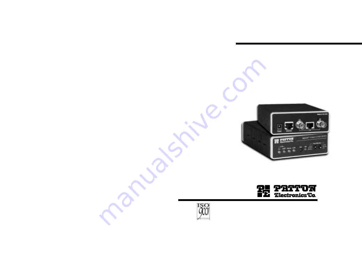
MODEL 2701/I
G.703/G.704 NTU with10Base-T Ethernet Interface
SALES OFFICE(301) 975-1000TECHNICAL SUPPORT(301) 975-1007http://www.patton.com
An ISO-9001
Certified Company
Part# 07M2701/I-DDoc# 086091UDRevised 11/20/00
Page 1: ...ODEL 2701 I G 703 G 704 NTU with 10Base T Ethernet Interface SALES OFFICE 301 975 1000 TECHNICAL SUPPORT 301 975 1007 http www patton com An ISO 9001 Certified Company Part 07M2701 I D Doc 086091UD Revised 11 20 00 ...
Page 2: ...ection from such interference in a commercial installation However there is no guarantee that interfer ence will not occur in a particular installation If the Model 2701 I does cause interference to radio or television reception which can be deter mined by disconnecting the cables the user is encouraged to try to correct the interference by one or more of the following measures moving the computin...
Page 3: ...peer protocol which can be broken into three main components 1 A standard method to encapsulate datagrams over serial links 2 A Link Control Protocol LCP to establish con figure and test the data link connection 3 A family of Network Control Protocols NCPs to establish and configure different net work layer protocols In order to establish communications over a point to point link each end of the P...
Page 4: ...equired If the foreign device requires authentication via PAP or CHAP the PPP software will respond with default Peer ID consisting of the units Ethernet MAC address and a password which consists of the unit s Ethernet MAC address Some networking systems do not define network numbers in packets sent out over a network If a packet does not have a specific destination network number a router will as...
Page 5: ...ansmits user data on all 32 time lots There is no framing information therefore the CRC4 MF SW2 2 switch is ignored In all other rate settings the unit employs G 704 framing TS0 is reserved for signaling SW1 6 and SW1 7 CLOCK MODES Network Clock Transmitter timing is derived using the received line signal received recovered from the network Internal Clock Transmitter timing is derived from an inte...
Page 6: ...g timeslot zero TS0 excessive errors may cause loss of frame or loss of sync If CRC 4 MF is used both units must be set for set for CRC 4 MF Otherwise the one using CRC 4 MF will detect loss of sync SW2 2 Option Off CRC 4 Disabled On CRC 4 Enabled 9 NOTE When the data rate is set to 2 048Mb s then the unit is forced into G 703 mode and it transmits user data on all 32 time lots There is no framing...
Page 7: ...CTING TO THE G 703 NETWORK The Power G 703 G 704 and Ethernet Line connections are located on the rear panel of the Model 2701 I Figure 5 below shows the location of each of these ports 5 1 1 Connecting Dual Coaxial Cable 75 ohm to the G 703 Network The Model 2701 I is equipped with dual female BNCs TX and RX for connection to a 75 ohm dual coax G 703 network interface If your G 703 G 704 network ...
Page 8: ... T network interface card construct a 10Base T crossover cable and connect the wires as shown in the dia gram below Figure 8 10BaseT Port 10Base T DTE RJ 45 Pin No RJ 45 Pin No 1 TD 1 TD 2 TD 2 TD 3 RD 3 RD 6 RD 6 RD 5 3 Connecting the 10Base T Ethernet Port to a Hub The 10Base T interface is configured as DTE Data Terminal Equipment just like a 10Base T network interface card in a PC Therefore it...
Page 9: ...urce 6 2 LED STATUS MONITORS The Model 2701 I features six front panel LEDs that monitor con nections on the G 703 G 704 and 10BaseT links signaling error and test modes Figure 11 below shows the front panel location of each LED Descriptions of each LED follow Figure 11 E1 Link Active Green Solid green On indicates that the end to end E1 Link is up signifying that the link is active The E1 Link LE...
Page 10: ...est mode by the local user or by the remote user 6 2 LOOP V 54 TELCO DIAGNOSTICS The Model 2701 I offers three V 54 loop diagnostics Use these diagnostics to test the NTU and any communication links These tests can be activated via the front panel switches 6 2 1 Operating Local Loopback LL The Local Loopback LL test checks the operation of the local Model 2701 I and is performed separately on each...
Page 11: ...ar all central office loops 6 2 4 Using the V 52 BER Test Pattern Generator To use the V 52 BER tests in conjunction with the Remote Digital Loopback tests or with Local Line Loopback tests follow these instructions 1 Locate the 511 511E toggle switch on the front panel of the 2701 I and move it UP This activates the V 52 BER test mode and transmits a 511 test pattern into the loop If any errors a...
Page 12: ...km 6 000 ft on 24 AWG Cable APPENDIX B ETHERNET 10BASE T SPECIFICATIONS DTE Interface 10Base T on RJ 45F DTE Data Rates 10Mbps LAN Connection RJ 45 10Base T 802 3 Ethernet Protocol PPP RFC 1661 with Bridging Control RFC 1638 MAC Address Table Size 4096 entries MAC Address Aging MAC addresses deleted after 8 minutes of inactivity Frame Buffer 512 Frames Frame Latency 1 frame Diagnostics V 54 Loopba...
Page 13: ...ton Model Description 270I B G 703 G 704 NTU with RS 530 interface 2701 C G 703 G 704 NTU with a V 35 interface 2701 D G 703 G 704 NTU with an X 21 interface 2701 I G 703 G 704 NTU with 10Base T ethernet interface 08055DCUI Universal Input Power Supply 07M2701 I User Manual 23 ...