USERM A N UA L
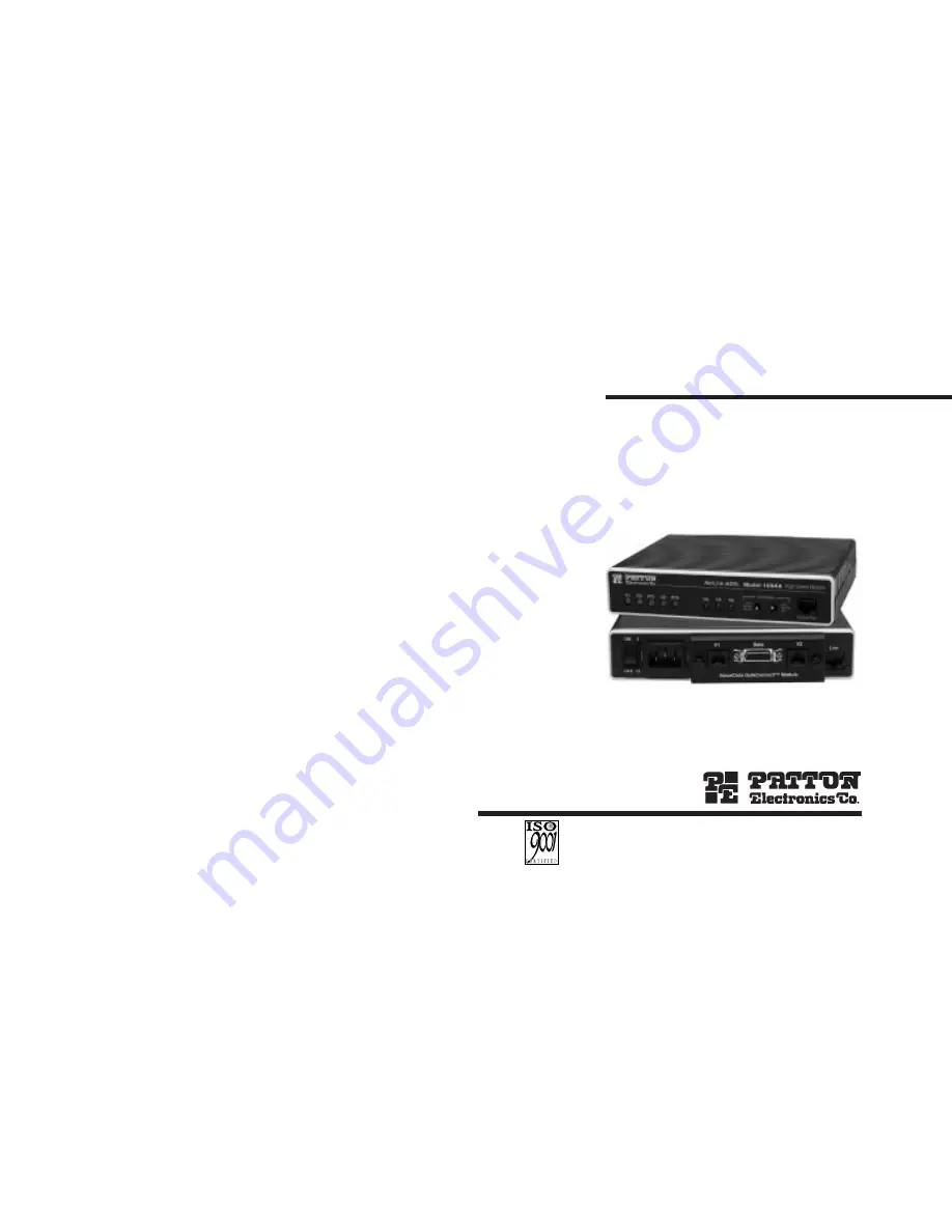
MODEL 1094A
NetLink™ HDSL
Multi-Rate Symmetric DSL Modem
Part# 07M1094A-BDoc# 032042UBRevised 07/22/99
SALES OFFICE(301)975-1000TECHNICAL SUPPORT(301)975-1007http://www.patton.com
C E R T I F I E D
An ISO-9001
Certified
Company
Page 1: ...094A NetLink HDSL Multi Rate Symmetric DSL Modem Part 07M1094A B Doc 032042UB Revised 07 22 99 SALES OFFICE 301 975 1000 TECHNICAL SUPPORT 301 975 1007 http www patton com C E R T I F I E D An ISO 900...
Page 2: ...s be liable for any damages incurred by the use of this product These damages include but are not limited to the following lost profits lost savings and incidental or consequen tial damages arising fr...
Page 3: ...S 2 2 DESCRIPTION The Patton Electronics NetLinkTM HDSL Multi Rate DSL Modem provides high speed 2 wire connectivity to ISPs PTTs and corpora tions using HDSL Multi rate Digital Subscriber Line techno...
Page 4: ...e Up of Configuration Switches all sets are identical in appearance Figure 1 Underside of Model 1094A Showing Location of DIP Switches Front Back On S3 S2 S1 Off 3 1 1 Configuration DIP Switch Set S1...
Page 5: ...nection rate The following table summarizes default positions of DIP Switch S3 Detailed descriptions of each switch follow the table Switch S3 1 DTE Rate Use Switch S3 1 through S3 6 to set the DTE b...
Page 6: ...r must have the same 2 Wire connection and DTE rate 2 To function properly the Model 1094A needs one twisted pair of metallic wire This twisted pair must be unconditioned dry metallic wire between 19...
Page 7: ...up with the socket inside the chassis 4 With the card edge contacts aligned with the socket firmly seat the module by using your thumbs to apply pressure directly to the right and left edges of the mo...
Page 8: ...ranging from 100 to 253 VAC with no re configuration necessary see Appendix B for available domestic and international power cords DC Power Supply option Model 1094A DC operates in 48 VDC environments...
Page 9: ...Wire Short Range Modem RD TD CTS CD DTR ER NS TM Test Modes Control Port Local Normal Remote 511E Normal 511 Figure 5 Model 1094A Front Panel ER blinks ON OFF after a 511 511E test has timed out See...
Page 10: ...rds the local DTE In a Remote Loop the data is looped back to the line but it is also allowed to pass through to the framer and to the remote DTE 17 Restart Procedure The restart procedure is in place...
Page 11: ...n the second path data presented at the far end DTE will be transmitted to the local DTE and then looped back within the local DTE Loop Control block with the Processor After the Local Loop is deselec...
Page 12: ...Request signal is sent to the remote unit The Remote unit then responds with an RDL Acknowledge command and the link is established Data originates at the local DTE and is looped at the Remote PROCESS...
Page 13: ...nds of the link Once a 511 511E pattern is selected on one end of the link the pattern generator will begin transmitting unframed 511 511E through the line to the Remote end A possible problem with th...
Page 14: ...nd ITU T X 21 Line Rates 144 272 400 528 784 1040 and 1168 kbps DTE Rates 64 128 192 256 320 384 448 512 576 640 704 768 832 896 960 1024 1088 and 1152 kbps Diagnostics V 52 compliant bit error rate p...
Page 15: ...Switzerland Power Cord 07M1090SVC 1090 Series Service Manual A AP PP PE EN ND DI IX X C C PATTON ELECTRONICS MODEL 1094A INTERFACE PIN ASSIGNMENTS RS 232 RS 530 Interface Pin Description DB 25 Female...
Page 16: ...T RD Receive Data B U XTC External Transmit Clock V RC Receive Timing W XTC External Transmit Clock X RC Receive Timing Y TC Transmit Clock A AA TC Transmit Clock B A AP PP PE EN ND DI IX X C C PATTO...
Page 17: ...3 4 5 4 1040 832 896 960 1024 11900 2 3 3 6 15500 2 9 4 6 1168 1088 1152 11000 2 1 3 3 15200 2 8 4 4 Line Rate DTE Rates kbps feet miles km feet miles km 144 64 128 18600 3 5 5 6 22100 4 2 6 7 272 192...