USER
MANUAL
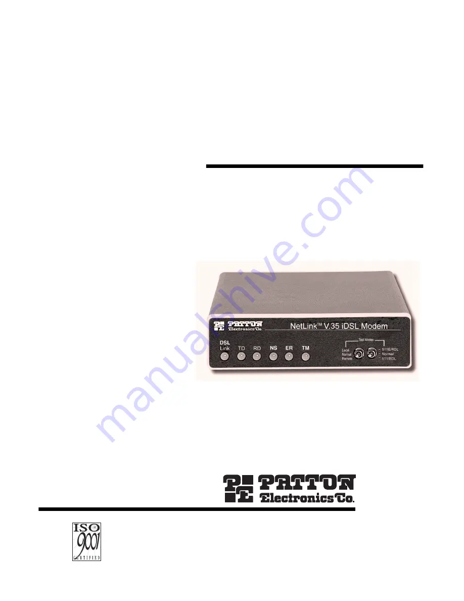
MODEL 1082 and1082/144
iDSL Modem with V.35 or X.21 Interface
SALES OFFICE(301) 975-1000TECHNICAL SUPPORT(301) 975-1007
Part# 07M1082-UMDoc# 03315U2-001Rev. CRevised 11/2/06
An ISO-9001
Certified
Company
C E R T I F I E D
Page 1: ...1082 and 1082 144 iDSL Modem with V 35 or X 21 Interface SALES OFFICE 301 975 1000 TECHNICAL SUPPORT 301 975 1007 Part 07M1082 UM Doc 03315U2 001 Rev C Revised 11 2 06 An ISO 9001 Certified Company C...
Page 2: ...itches S2 1 19 2 kbps or 144 kbps Synchronous Rate Enable 13 Switch S2 2 Front Panel Switch Disable 13 Switches S2 3 Response to Local Line Loop Requests from DTE 13 Switches S2 4 and S2 5 Not Assigne...
Page 3: ...ates 25 A 6 Diagnostics 25 A 7 LED Status Indicators 25 A 8 Connectors 26 A 9 Power 26 A 10 Temperature Range 26 A 11 Altitude 26 A 12 Humidity 26 A 13 Dimensions 26 A 14 Weight 26 A 15 Line Interface...
Page 4: ...ant to Part 15 of the FCC Rules These limits are designed to provide reasonable protection against harmful interfer ence when the equipment is operated in a commercial environment This equipment gener...
Page 5: ...s number may be obtained from Patton Electronics Technical Service at Tel 301 975 1007 E mail support patton com URL www patton com Note Packages received without an RMA number will not be accepted Pa...
Page 6: ...e Symmetric DSL V 35 and X 21 Interfaces Compatible with Popular Model 1092 SNMP Manageable with 1092ARC and 1001MC as 1001MC SNMP Agent Rack Card Universal Power Options 120VAC 230VAC and 48VDC Avail...
Page 7: ...1082 144 are SNMP manageable when con nected to a rack mounted Model 1092ARC see Figure 1 SNMP manage ment is enabled through a 1001MC rack management card located in the Patton Electronics Rack Syste...
Page 8: ...THE HARDWARE DIP SWITCHES Using a small flat tip screwdriver remove the protective cover located on the underside of the Model 1092 see Figure 2 Figure 2 Removing the cover to access DIP switches S1...
Page 9: ...S1 1 through S1 8 Detailed descriptions of each switch follow the table S1 S2 1 2 3 4 ON 5 6 7 8 1 2 3 4 ON 5 6 7 8 1 2 3 4 ON 5 6 7 8 Push toggle up for ON position Switch toggle Push toggle down fo...
Page 10: ...e 144 kbps synchronous rate To operate at these rates set switches S1 1 and S1 2 both to the OFF position and Switch S2 1 to the ON position see section Configuring DIP switch S2 on page 122 for a des...
Page 11: ...o so by the far end Model 1082 or Model 1082 144 For example when switch S1 8 is set to ON it will enter RDL mode See section 5 3 Test Modes on S1 4 Setting On Reserved S1 5 Setting Off Async Sync S1...
Page 12: ...switches S2 1 through S2 8 Detailed descriptions of each switch follow the table S1 8 Setting On Response to RDL Request Enabled Off Response to RDL Request Disabled 144 kbps data rate is only availab...
Page 13: ...tch S2 3 to enable Local Line Loopback from the local DTE inter face See Local Line Loopback LLB on page 22 Switches S2 4 and S2 5 Not Assigned 144 kbps data rate is only available on the Model 1082 1...
Page 14: ...Compatability Mode In some instances you may need to connect a Model 1082 to a third party IDSL modem By enabling S2 7 the 1082 will negotiate and link up to a non Patton IDSL Modem When using two Pat...
Page 15: ...s Both units at the end of the twisted pair DSL span must be set for the same DTE rate 2 To function properly the Model 1082 needs one twisted pair of metallic wire This twisted pair must be unconditi...
Page 16: ...DCE this interface is designed to connect to DTE equipment such as a router When connect ing the V 35 interface of the Model 1082 to your DTE device use a V 35 straight through cable see Figure 6 App...
Page 17: ...e Model 1082 to V 35 serial DCE 4 3 CONNECTING THE MODEL 1082 X 21 SERIAL INTERFACE Model 1082 supports X 21 serial port connections This section describes how to connect the serial ports to your X 21...
Page 18: ...ition DCE you must open the case Model 1082 case Opening the Case To open the Model 1082 case insert a flat head screw driver into an open slot on both sides of the case as shown in Figure 9 Twist the...
Page 19: ...Universal AC Power 100 240VAC The Model 1082 uses a 5VDC 2A universal input 100 240VAC power supply center pin is 5V The universal input power supply has a male IEC 320 power entry connector This powe...
Page 20: ...11 Figure 11 Connecting DC power to the 48V PSM3 DC power supply z WARNING There are no user serviceable parts in the power supply section of the Model 1082 Fuse replacement should only be performed b...
Page 21: ...D See also LED description Table 1 Figure 12 Model 1082 front panel Table 1 LED descriptions DSL Link Active Green Solid green On indicates that the end to end DSL Framer Link is up signifying that th...
Page 22: ...opback To perform an LLB test follow these steps 1 Activate LLB This may be done in one of three ways Move the front panel toggle switch up to Local Raise the LLB signal on the interface see Appendix...
Page 23: ...ignal on the interface see Appendix C Model 1082C and 1082D Interface Pin Assignments on page 28 Note Remote loopback cannot be activated until approximately 45 seconds after the two modems have linke...
Page 24: ...52 BER test mode and transmits a 511 test pattern into the loop If any errors are present the local modem s red ER LED will blink continuously 2 If the above test indicates that no errors are present...
Page 25: ...5 km on 26 AWG 0 4mm wire A 5 DATA RATES Synchronous 19 2 32 56 64 128 and 144 kbps Asynchronous 0 38 4 kbps A 6 DIAGNOSTICS V 52 compliant bit error rate pattern 511 511E pattern generator and detect...
Page 26: ...50 60 Hz universal input option 48 VDC option 5 watts A 10 TEMPERATURE RANGE 32 122 F 0 50 C A 11 ALTITUDE 0 15 000 feet 0 4 572 meters A 12 HUMIDITY 5 to 95 non condensing A 13 DIMENSIONS 4 125W x 1...
Page 27: ...rate of 144 kbps 48V PSM DC Power Supply Module 08055DCUI 100 240VAC 5V 5 reg DC 2A Universal Input Adapter 0805EUR European Power Cord CEE 7 A 0805UK United Kingdom Power Cord D 0805US American Power...
Page 28: ...ource H DTR Data Terminal Ready DTE Source L LLB Local Line Loop DTE Source M TM Test Mode DTE Source N RDL Remote Digital Loop DTE Source P TD Transmit Data DTE Source R RD Receive Data DCE Source S...
Page 29: ...TE Source 3 C Control A DTE Source 4 R Receive Data A DCE Source 5 I Indication A DCE Source 6 S Signal Element Timing A DCE Source 7 BT Byte Timing A DCE Source 8 SGND Signal Ground 9 T Transmit Data...
Page 30: ...DCE Configuration Pin Signal 1 Frame Ground 2 T Transmit Data A 3 C Control A 4 R Receive Data A 5 I Indication A 6 S Signal Element Timing A 7 BT Byte Timing A 8 SGND Signal Ground 9 T Transmit Data...
Page 31: ..._________________ _________________________________________________________ _________________________________________________________ _________________________________________________________ ________...
Page 32: ..._______________________________________ _________________________________________________________ _________________________________________________________ ____________________________________________...