U
USSEERR
M
MAAN
NU
UAALL
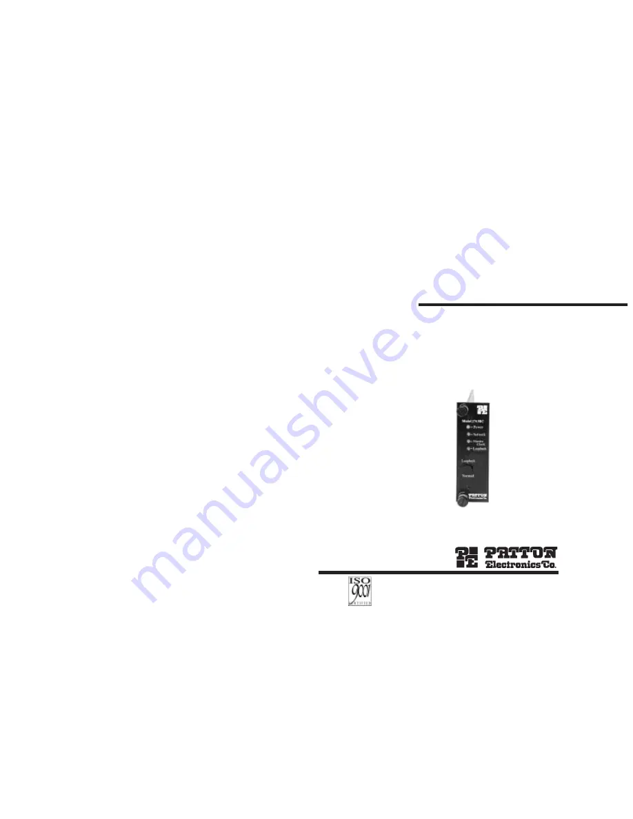
MODEL 2703RC-A
MegaLink-1™
G.703/E1 Digital Modem:
Rack Mount Card
SALES OFFICE
(301) 975-1000
TECHNICAL SUPPORT
(301) 975-1007
http://www.patton.com
Part# 07M2703RC-A-A
Doc# 031122UA
Revised 2/4/99
An ISO-9001
Certified Company


