P-K Storm
TM
Gas Fired Boiler
Technical Service 1.877.728.5351
Revised: June 26, 2020
Released: June 26, 2020
©
Patterson-Kelley 2020
All Rights Reserved.
2691000273 P-K Storm ST2500-ST4000
Installation and Owners Manual Rev A.docx
Page 43
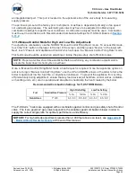
In order to test the low water cut-out, press and hold the red
“Push to Test” button for at least 5 seconds.
A manual lockout reset error displaying
10010:
“Low Water Limit”
on the NURO touchscreen should
occur. The red LED indicator on the Low Water cut-off will no longer be illuminated.
Optional Test Method:
First turn the boiler of
f, and then turn off the boiler’s circulating pump.
Isolate the boiler from the system. Drain the water level below the low water cut-off probe. Turn
the boiler back on. It should not operate, and a manual lockout reset error displaying
10010:
“Low Water Limit”
on the NURO touchscreen should occur. The red LED indicator on the Low
Water cut-off will no longer be illuminated.
Return the system to normal operation by
refilling with water, restarting the boiler’s circulating pump,
and then turning the boiler back on.
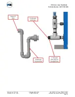
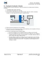
Flow Switch Test
The appliance is equipped with a paddle type flow switch installed in the hot water outlet piping.
In order to test the flow switch, provide a call for heat to the appliance. Once the appliance has begun
its pre-purge sequence, stop the water flow by closing an isolation valve or turning off the circulation
pump. The NURO control should display a “HOLD” error and not allow the appliance to proceed to
ignition. Re-establish flow through the appliance by reopening the isolation valve or turning on the
circulation pump.
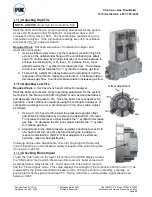
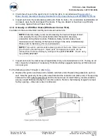
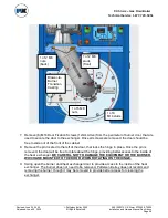
Manual Reset High Temperature Limit Test
The boiler is furnished with two manual reset high temperature limits. Both probes are installed near the
boiler’s outlet in order to measure the outgoing supply water temperature. Each probe is connected to
a manual reset high temperature limit by a thin, metal capillary tube. The first high temperature limit
switch is located inside the boiler’s front door, towards the left of the control panel and is identified with
a label.
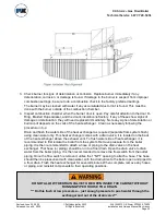
The second high temperature limit switch is located inside the boilers’ first left side panel, in
front of the gas valve, in the water outlet manifold. These high temperature limit switches are wired in
series; thus tripping either switch will result in the unit displaying an error. In the case of the NURO
touchscreen displaying 100009: “
High Temperature Limit”
both high temperature limit switches will
need to be manual reset.
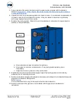
Test each of the manual reset high temperature limit controls as follows:
1. Cycle the boiler on by generating a heat request.
2. Allow the boiler to proceed through ignition until main flame is established.
3. Using a flathead screwdriver, turn down the setting on the manual reset high temperature limit
to its lowest value. Turning the screwdriver counter-clockwise decreases the temperature
setting.
4. When the outgoing supply water temperature exceeds the setting on the manual reset high
temperature limit, the main burner will shut off.
5. The NURO touchscreen will display 10009:
“High Temperature Limit”
. Return the system to
normal operation by readjusting the setting on the manual reset high temperature limit to its
default setting, press the reset button on the manual reset high temperature limit, and finally
touch any prompts from the NURO control.
These manual reset high temperature limits are wired in series so if only one switch trips, it would result
in the unit locking out.