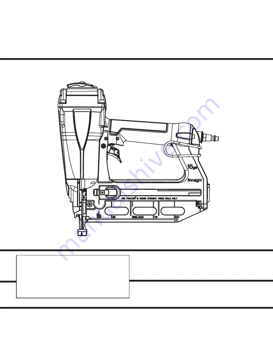
MODEL T250S-F16
16 Gauge Straight
Finish Nailer
IMPORTANT!
DO NOT DESTROY
It is the customer’s responsibility to have all
operators and service personnel read and
understand this manual.
OPERATING MANUAL AND
TOOL SCHEMATIC
P
Page 1: ... F16 16 Gauge Straight Finish Nailer IMPORTANT DO NOT DESTROY It is the customer s responsibility to have all operators and service personnel read and understand this manual OPERATING MANUAL AND TOOL SCHEMATIC P P ...
Page 2: ...ations This tool will deliver efficient dependable performance when used according to the manufactures guidelines Please study this manual including the safety instructions to fully understand the operation of this tool TOOL AND FASTENER SPECIFICATIONS 3 SAFETY INSTRUCTIONS 4 TOOL OPERATION 5 EXPLODED VIEW AND SPARE PARTS LIST 10 11 ACCESSORIES 12 ...
Page 3: ...uses a 1 4 N P T male plug The inside diameter should be 28 7mm or larger The fitting must be capable of discharging tool air pressure when disconnected from the air supply OPERATING AIR PRESSURE 80 to 120 p s i 5 5 to 8 3 bars Select the operating air pressure within this range for best tool performance DO NOT EXCEED THIS RECOMMENDED OPERATING PRESSURE NAIL LENGTH 3 4 2 1 2 SHANK DIAMETER 16 gaug...
Page 4: ...th a safety mechanism called a work contacting element to help prevent accidental firing Never tamper with disable or remove the work contacting element Do not use the tool unless the work contacting element is working properly The tool could fire unexpectedly DISCONNECT THE TOOL WHEN NOT IN USE Always disconnect the tool from the air line when it is not in use when you leave the work area or when...
Page 5: ...ck the tool simply reload another strip of nails Depth of Drive Adjustment Disconnect the air supply The depth of drive adjustment is done by turning the adjustment wheel as shown by the arrows on the side of the tool Clearing a Jam An occasional problem you may encounter is a jammed fastener Because of the unique design of the Paslode Finish Nailer clearing a jammed fastener is easy 1 Disconnect ...
Page 6: ...contacing element against the workpiece position ing the tool above as carefully as possible When the desired number of fasteners have been driven release the tool trigger to avoid unintentional fastener discharge 6 Reversible Belt Hook The belt hook can be changed from the left hand side of the tool to the right hand side To change the position squeeze the base of the belt hook and remove it from...
Page 7: ...in the tank will keep the air free of frost Testing the Tool After Servicing After replacing any part or parts it is important to check the tool for proper operation This ensures that the tool was put together correctly is safe to use and will perform the job properly Ensure that all hardware is tight Ensure that the work contacting element is installed correctly in relation to the trigger and tha...
Page 8: ...ricated Prevent clogging of filter with dirt Prevent air leakage and pro mote efficient operation Promote operator safety and efficient tool operation Prevent jamming of fasteners Assure long life and proper operation of tool Keep tool operating efficiently and maintain Paslode tool warranty Open manual petcock most air supply systems have such a valve Fill with Paslode pneumatic tool lubricant Pa...
Page 9: ...ir lines 3 8 inch ID minimum Adjust the depth of drive adjustment extend length Reduce air pressure Open front guide latch release jammed fastener and close latch securely Check magazine for proper fasteners Magazine follower should slide freely Clean as needed to remove debris Make sure correct fasteners are being used Use fasteners that meet Paslode specifications only Increase air flow to tool ...
Page 10: ...11 501908 1 Collar 12 501909 1 Packing 13 501910 1 Piston Ring 14 501911 1 O Ring 15 501912 1 Driver Blade 16 501920 1 Cylinder Press Ring 17 501913 1 O Ring 18 501914 1 Cylinder 19 501915 1 Cylinder Ring 20 501916 1 Cylinder Spacer 21 501917 1 O Ring 22 501918 1 Bumper 23 501919 1 Driver Guide 24 501921 1 O Ring 25 501922 1 O Ring 26 501923 1 Plunger Cap 27 501930 2 Spring Pin 28 501924 1 Valve P...
Page 11: ...50 51 52 53 54 55 56 57 58 59 60 61 62 63 65 66 67 68 69 70 71 75 74 72 76 77 78 79 80 81 82 83 64 73 Driver Blade Assembly 501987 Trigger Valve Assembly 501988 87 86 84 85 WARNING All parts must be periodically inspected and replaced if worn or broken Failure to do this can affect the tool s operation and present a safety hazard Assembly Hardware System Metric 88 ...
Page 12: ... Cleaner 48 3 9 1 2 o N t r a P s l o o t e d o l s a P l l a r o f r e n a e l c l a e d I Safety Glasses 382 1 0 4 o N t r a P r a e l C ACCESSORIES An Illinois Tool Works Company 888 Forest Edge Drive Vernon Hills Illinois 60061 8117 2010 Illinois Tool Works Inc 501977 3 04 10 Tool Case Handy carrying case that conveniently stores your tool 8 7 9 1 0 5 o N t r a P s e i r o s s e c c a l a n o ...