012-06379B
Instruction Manual andExperiment Guide forthe PASCO scientificModel ME-9215B
Includes
Teacher’s Notes
and
Typical
Experiment Results
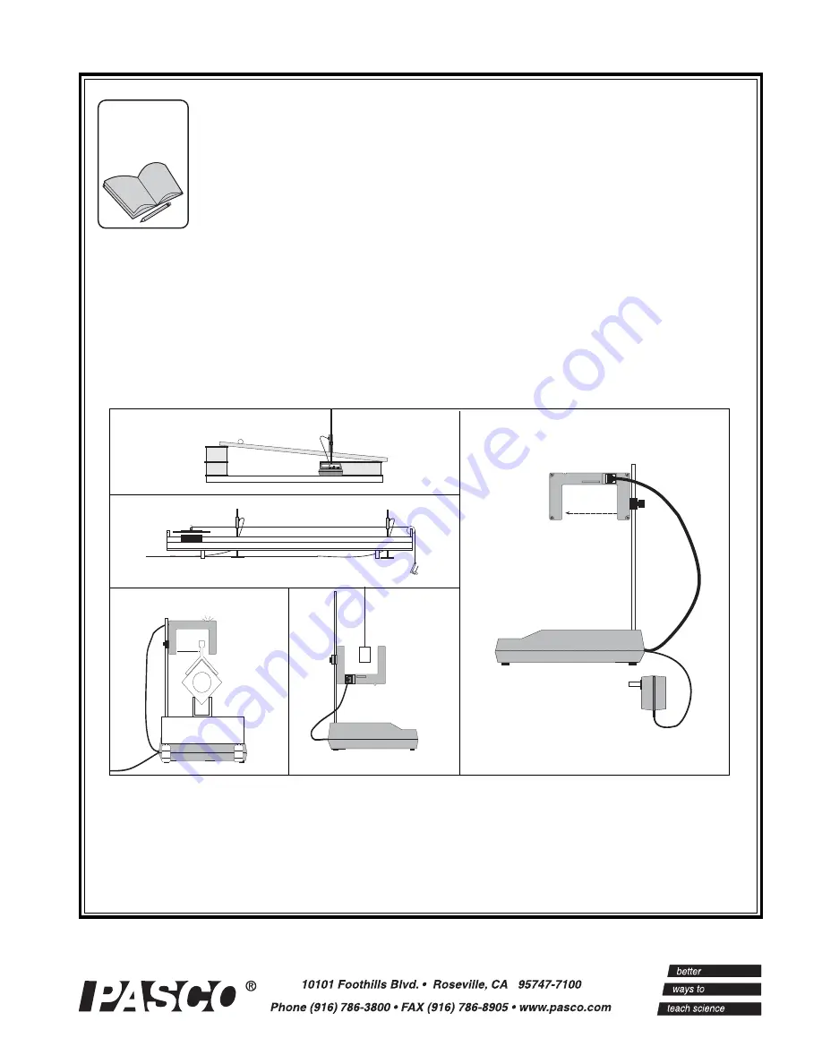
PHOTOGATE TIMER
Page 1: ...012 06379B Instruction Manual and Experiment Guide for the PASCO scientific Model ME 9215B Includes Teacher s Notes and Typical Experiment Results PHOTOGATE TIMER ...
Page 2: ......
Page 3: ...neous vs Average Velocity 5 Experiment 2 Kinematics on an Inclined Plane 7 Experiment 3 Speed of a Projectile 9 Experiment 4 Newton s Second Law 11 Experiment 5 The Force of Gravity 13 Experiment 6 Conservation of Momentum 15 Experiment 7 Kinetic Energy 17 Experiment 8 Conservation of Mechanical Energy 19 Experiment 9 Elastic Kinetic Energy 21 Experiment 10 Pendulum Motion 23 Teachers Guide 27 Mai...
Page 4: ... used only in their laboratories and classrooms and are not sold for profit Reproduction under any other circumstances without the written consent of PASCO scientific is prohibited Limited Warranty For a description of the product warranty see the PASCO catalog Technical Support For assistance with any PASCO product contact PASCO at Address PASCO scientific 10101 Foothills Blvd Roseville CA 95678 ...
Page 5: ...RT STOP button that lets you use the timer as an electronic stopwatch An important addition to your Photogate Timer is the ME 9204B Accessory Photogate which must be ordered separately It plugs directly into the Photogate Timer and triggers the timer in the same manner as the built in pho togate In Pulse Mode the Accessory Photogate lets you measure the time it takes for an object to travel betwee...
Page 6: ...mer measures the time between successive interruptions of the photogate Tim ing begins when the beam is first blocked and continues until the beam is unblocked and then blocked again With an Accessory Photogate plugged into the Photogate Timer the timer will measure the time it takes for an object to move between the two photogates Pendulum Mode In Pendulum mode the timer meas ures the period of o...
Page 7: ...imer in Gate mode push the object through the photogate along the path it will fol low in the experiment d When the photogate is triggered the LED on top of the photogate comes ON measure the position of the object relative to an external reference point e Continue pushing the object through the photo gate When the LED goes OFF measure the posi tion of the object relative to the same external ref ...
Page 8: ...lls of differ ent size and mass a release mechanism and a receptor pad The release mechanism and the receptor pad auto matically trigger the timer so you get remarkably accu rate measurements of the free fall time of the steel ball ME 9259A Laser Switch This highly collimated photodetector is identical to a photogate except that you use a laser not included as the light source You can now time the...
Page 9: ...k as shown in Figure 1 1 elevating one end of the track with a 1 2 cm support d Choose a point x1 near the center of the track Measure the position of x1 on the air track metric scale and record this value in Table 1 1 If you are using an air track with out a scale use a meter stick to measure the distance of x1 from the edge of the upper end of the track e Choose a starting point x0 for the glide...
Page 10: ...calculate the average of t1 through t5 Record this value as tavg d Calculate vavg D tavg This is the average velocity of the glider in going between the two photogates e Plot a graph of vavg versus D with D on the x axis x1 D t1 t2 t3 t4 t5 tavg vavg Questions c Which of the average velocities that you measured do you think gives the closest approximation to the instantaneous velocity of the glide...
Page 11: ...a pencil on the side of the channel Then determine the point at which the ball last triggers the timer and mark this point also Measure the distance between these marks and record this dis tance as Δ Δ Δ Δ Δd Determine the mid point of this interval and mark it in pencil on the side of the channel e Set the Photogate Timer to GATE mode and press the RESET button f Move the ball to a point 5 cm alo...
Page 12: ...for motion with a constant acceleration starting from rest include x 1 2 at2 and v at Eliminate t from these equations to determine the relationship between x and v Using your result and your graph can you determine the acceleration of the ball as it rolled down the plane d From your answer to question 1 write the equation of motion for the accelerating ball giving its position as a function time ...
Page 13: ...nd compare that with a value calculated by examining the motion of the projectile Procedure c Set up the apparatus as in figure 3 1 so the ball rolls down the ramp onto the table then passes through the photogate interrupting the beam d Tape a piece of paper to the table under the Accessory Photogate Use the ramp to push the ball slowly through the Accessory Photogate as shown in Figure 3 2 Deter ...
Page 14: ...lso record the average distance as dx in the space provided to the right of the table Table 3 1 Data from Photogate Timer Trial Time Distance 1 2 3 4 5 Averages v0 avg Δ Δ Δ Δ Δd Vertical height dy Average horizontal distance dx Horizontal velocity v0 Percentage difference d Divide Δ Δ Δ Δ Δd by your average time to determine v0 the velocity of the ball just before it left the table e Now determin...
Page 15: ...ider but it should not accelerate steadily in either direction d Measure the effective length of the glider and record your value as L in Table 4 1 e Mount the hook into the bottom hole of the cart To counterbalance its weight add a piece of similar weight on the opposite end as shown on Fig 4 1 f Add 50 60 grams of mass to the glider using 10 or 20 gram masses Be sure the masses are distributed s...
Page 16: ...mine v1 and v2 the average glider velocity as it passed through each photogate d Use the equation a v2 v1 t3 to determine the average acceleration of the glider as it passed between the two photogates e Determine Fa the force applied to the glider by the hanging mass Fa ma g g 9 8 m s2 980 cm s2 Analysis c Draw a graph showing average acceleration as a function of applied force Fa d Draw a second ...
Page 17: ...upport legs Record this distance in the space on the following page e Place a block of thickness h under the support leg of the track Measure and record h on the following page For best results measure h with calipers f Measure and record D the distance the glider moves on the air track from where it triggers the first photogate to where it triggers the second photogate Move the glider and watch t...
Page 18: ...lerations calculate the force acting on the glider along its line of motion F maavg h For each measured value of F use the equation F Fg sin θ θ θ θ θ to determine Fg i Construct a graph of Fg versus m with m as the independent variable x axis Analysis Does your graph show a linear relationship between Fg and m Does the graph go through the origin Is the gravitational force acting on the mass prop...
Page 19: ...elastic collision Carefully level the track d Measure m1 and m2 the masses of the two gliders to be used in the collision Record your results in Table 6 1 e Measure and record L1 and L2 the length of the gliders e g push glider1 through photogate1 and measure the distance it travels from where the LED comes on to where it goes off again f Set both Photogate Timers to GATE mode and press the RESET ...
Page 20: ...estions L1 L2 Table 6 1 Data and Calculations c Was momentum conserved in each of your collisions If not try to explain any discrepancies d If a glider collides with the end of the air track and rebounds it will have nearly the same mo mentum it had before it collided but in the opposite direction Is momentum conserved in such a collision Explain e Suppose the air track was tilted during the exper...
Page 21: ...cord your results in Table 7 1 e Measure and record L1 and L2 the length of the gliders e g push glider1 through photogate1 and measure the distance it travels from where the LED comes on to where it goes off again f Set both Photogate Timers to GATE mode and press the RESET buttons g Place glider2 at rest between the photogates Give glider1 a push toward it Record four time mea surements in Table...
Page 22: ...cities If you are using a PASCO air track replace the bumpers with the wax and needle Otherwise velcro fasteners can be used with most gliders h Repeat the experiment several times varying the mass of one or both gliders and varying the initial velocity of glider1 i Try collisions in which the initial velocity of glider2 is not zero You may need to practice a bit to coordinate the gliders so the c...
Page 23: ...the gain in kinetic energy Stated mathematically ΔEk Δ mgh mgΔh where Ek is the change in kinetic energy of the glider ΔEk 1 2 mv2 2 1 2 mv1 2 and Δ mgh is the change in its gravitational potential energy m is the mass of the glider g is the acceleration of gravity and Δh is the change in the vertical position of the glider Procedure c Level the airtrack as accurately as possible d Measure d the d...
Page 24: ...e different masses recording the mass m for each set of measurements If you have time you may also want to try changing the height of the block used to tilt the track or the distance between the photogates d h D L m Table 8 1 Data and Calculations m θ t1 t2 v1 v2 Ek1 Ek2 Δ mgh Data and Calculations c Calculate θ the angle of incline for the air track using the equation θ arctan h d For each set of...
Page 25: ...he end of the track and attach it to a hanger d Hang masses on the hanger and determine how far the spring stretches This is easily done using the metric scale on the side of the air track and using the glider to monitor the distance the spring has extended Record the masses added and the position of the glider in Table 9 1 The air flow should be on while gathering this data Then remove the hanger...
Page 26: ...ph in newtons meter is equal to k d For each set of trials you performed for a given spring stretch and glider mass divide Δd by your average time to determine the average velocity of the glider as it passed through the photogate Calculate the final kinetic energy of the glider 1 2 mv2 e Calculate the energy stored in the spring in each case 1 2 kx2 where k is the spring constant and x is the spri...
Page 27: ...he bob swinging but keep the swings relatively small h Press the RESET button on the Timer Note the first time displayed This is the period of the pendulum the time for one complete oscillation Repeat this measurement sev eral times by pressing the RESET button and recording the first time measured Take the average of these measured times to determine T the period of the pendulum Record T in Table...
Page 28: ...bob so the pendulum oscillates Record the first times you see on the timer display This is the time during which the bob blocked the photogate beam as it passed through the pho togate Repeat this measurement several times starting the bob from the same height each time Take the average of your measured times and record this value as t in Table 10 2 i Change the starting height of the bob and repea...
Page 29: ...the period of your pendulum vary with the mass of the bob Discuss why it did or did not e Was mechanical energy conserved during a single swing of the pendulum f No matter how high the initial height of the bob the pendulum ultimately slows down and stops Does this slowing down defy the principle of the conservation of energy Explain L Table 10 2 θ t Δh ΔU Ek deg S m J J Δd m m Kg m ...
Page 30: ...26 Photogate Timer 012 06379B ...
Page 31: ...ity becomes a closer approximation to the instantaneous velocity when the distance be tween the photogates is reduced d Yes The maximum error can be evaluated using the standard deviation or best fit methods e Timer accuracy has the greatest impact on the accu racy of velocity measurements The ability to measure small time intervals accurately will allow a better ap proximation of the instantaneou...
Page 32: ...elled by the ball down the incline plane The mathematical relationship being depicted by the plot is vf 2 vi 2 0 861 D Answers to Questions c Yes a 0 43 m s2 d This is because time can be accurately measured This is nottrue for velocity and accceleration for complex motions Distance t1 t2 t3 t4 Average Final Travelled Time Velocity cm s s s s s m s 5 0 07 0 07 0 07 0 07 0 07 0 22 10 0 05 0 05 0 05...
Page 33: ...slide forward until the weight hanger nearly reaches the ground e Mount the hook into the bottom hole of the glider To counterbalance its weight add an accessory with simi lar weight to the opposite end of the glider as shown The tables below list the results from two experimental conditions The value of each parameter was the average derived after five trials Δd cm 1 60 Trial Time dx dy s cm cm 1...
Page 34: ...ion is defined as change of velocity per unit of time As the incremental time period or the length of the object being measured becomes sufficiently small the acceleration being measured will become a better approximation of the instantaneous accelearation One way to include instantaneous accelearation in the axperiement is to reduce the distance between the photogates M Ma t1 t1 t2 t2 t3 v1 v2 a ...
Page 35: ... 0 57 0 22 0 36 0 57 0 12 1 84 220 2 0 35 0 57 0 22 0 36 0 57 0 12 2 03 240 3 0 35 0 57 0 22 0 36 0 57 0 12 2 23 Table 5 2 d cm 100 D cm 80 h cm 2 6 L cm 12 6 θ 0 026 rad m t1 t1 t2 t2 v1 v2 aavg Fg g s s s m s m s m s 2 N 180 2 0 25 0 40 0 16 0 51 0 80 0 24 1 67 220 2 0 25 0 41 0 16 0 51 0 80 0 24 2 00 261 6 0 25 0 41 0 16 0 51 0 80 0 24 2 43 Exp 5 The Force of Gravity Notes on Analysis c Yes Yes...
Page 36: ... initially Stationary L1 12 6 cm L2 12 8 cm Distance Between Photogates 79 8cm m1 m2 t1i t2i t1f t2f v1i v2i v1f v2f Pi Pf Error g g s s s s m s m s m s m s kg m s kg m s 180 2 201 3 0 275 N A 3 81 0 318 0 46 0 0 03 0 40 0 08 0 08 9 08 180 2 201 3 0 33 N A 4 267 0 381 0 38 0 0 03 0 34 0 07 0 06 9 44 180 2 201 3 0 242 N A 3 369 0 278 0 52 0 0 04 0 46 0 09 0 09 8 40 180 2 201 3 0 295 N A 3 43 0 341 ...
Page 37: ...nts out the fact that mommentum is always loss not gained The increased in momentum in one or two cases is due to additional influ ences such as gravitational introduced by unlevelled airtrack m1 m2 t1i t2i t1f t2f v1i v2i v1f v2f Pi Pf Error g g s s s s m s m s m s m s kg m s kg m s 180 2 261 3 0 362 0 422 0 312 0 589 0 35 0 303 0 40 0 22 0 02 0 02 3 31 180 2 261 3 0 353 0 427 0 313 0 568 0 36 0 ...
Page 38: ...1 12 92 180 2 201 3 0 242 N A 3 369 0 278 0 52 0 0 04 0 46 0 02 0 02 12 12 180 2 201 3 0 295 N A 3 43 0 341 0 43 0 0 04 0 38 0 02 0 01 12 98 180 2 201 3 0 239 N A 3 635 0 274 0 53 0 0 03 0 47 0 03 0 02 11 85 180 2 261 5 0 492 N A 3 956 0 637 0 26 0 0 03 0 20 0 01 0 01 9 11 180 2 261 5 0 38 N A 2 597 0 481 0 33 0 0 05 0 27 0 01 0 01 4 39 180 2 261 5 0 243 N A 1 513 0 309 0 52 0 0 08 0 41 0 02 0 02 ...
Page 39: ...3 0 435 0 778 0 26 0 21585 0 29 0 16 0 01 0 01 8 63 L1 12 8 cm L2 12 6 cm Distance Between Photogates 60cm Exp 8 Conservation of Mechanical Energy Notes on Analysis The tables below list the typical results for the experiment performed at two different incline angles Notes on Questions c Yes d In most cases there was a slight loss of kinetic energy due to existence of slightly inelastic colli m1 m...
Page 40: ... to experiemental error as well measurement as loss of energy due to friction between gliders and air track Figure 9 1 Spring Constant Notes on Analysis The results of the each portion of the experiement is pre sented to the right Table 9 2 Potential Energy vs Kinetic Energy of Spring Mass System X1 104 2 cm K 7 52 N m Flag Width 3 8 cm m Spring Stretch tavg vavg K E P E Error g cm s m s J J 211 5...
Page 41: ...ogate Timer 37 Exp 10 Pendulum Motion Notes on Analysis Part 1 Period of Oscillation versus Mass and Length The graphs below present the relationship between period and length of oscillation for four different masses ...
Page 42: ...er Photogate Timing System θ Δh t Δu Ek of diff deg cm s J J 15 3 41 0 00 0 06 0 07 11 97 20 6 03 0 00 0 10 0 11 3 50 25 9 37 0 00 0 16 0 16 0 00 30 13 40 0 00 0 23 0 21 6 96 35 18 08 0 00 0 31 0 30 2 55 Notes Questions c From the graphs there exist a linear relationship between period and the squared root of the length of oscillation This relationship remained unchanged despite changes in mass of...
Page 43: ...out the bottom panel d Remove the thumb screw which holds the battery re tainer plate then lift out the retainer plate and the bat teries e Replace with four new C size 1 5 VDC batteries Be sure the polarity is as shown on inside of the case f Replace the battery retainer plate and the bottom panel CAUTION Do not store the timer with the batteries installed The batteries may leak and dam age the t...
Page 44: ......