®
PASCO Structures Systems
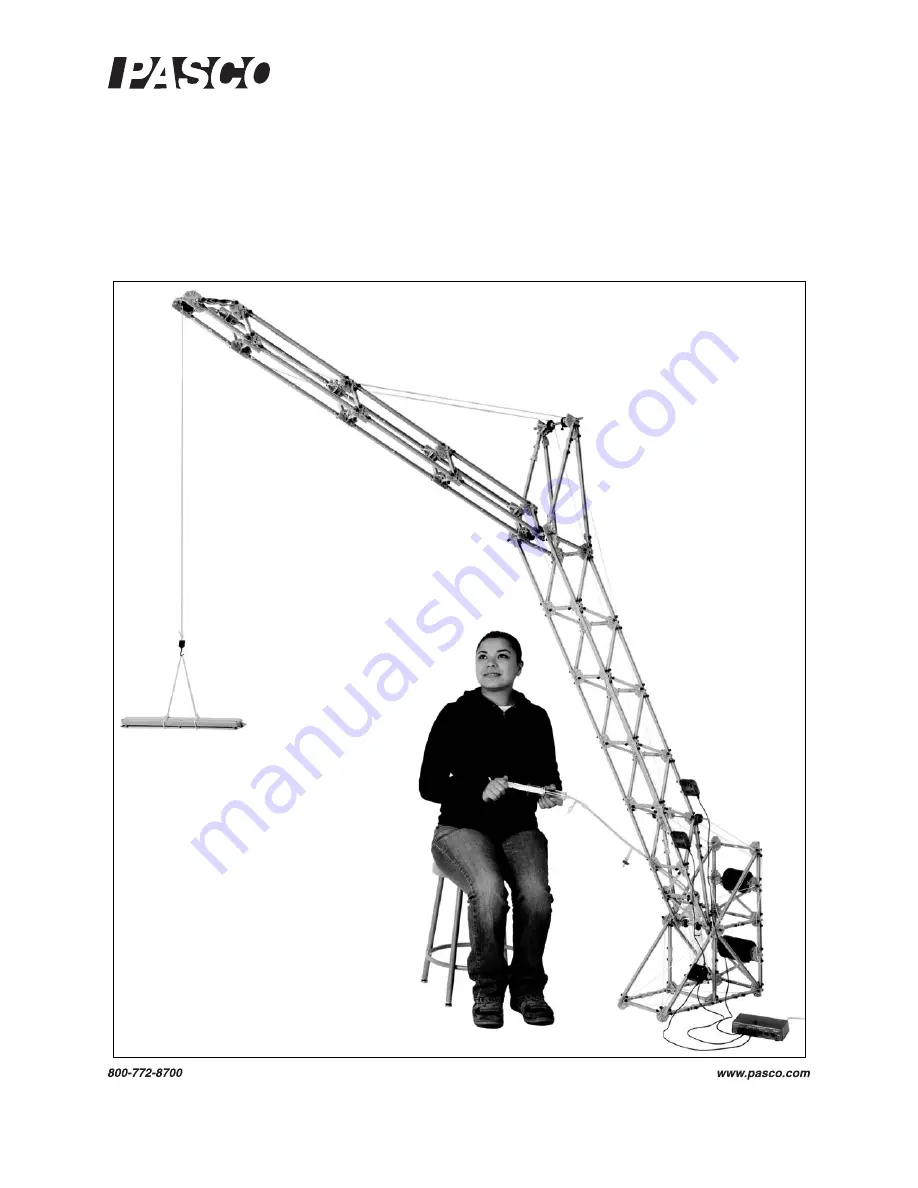
Large Structures Set
ME-7003
I n s t r u c t i o n M a n u a l
0 1 2- 1 2 67 0 A
*012-12670*
Page 1: ... PASCO Structures Systems Large Structures Set ME 7003 Instruction Manual 012 12670A 012 12670 ...
Page 2: ...tures Set The picture shows Load Cells a Load Cell Amplifier Large Slotted Masses and the Hydraulics Structures Set which are available separately The ME 7003 Large Structures Set can be used to build over a dozen different models Instructions for building twenty models are included in this manual ...
Page 3: ...le Stayed Bridge 13 3 Arch Truss Bridge 15 4 Roller Coaster 17 5 Canyon Car Jump 20 6 Suspension Bridge 22 7 High Road Low Road 24 8 Tied Arch Bridge 26 9 Baltimore Bridge 28 10 Double Tied Arch Bridge 31 11 Cantilever Truss Bridge 33 12 Brachistochrone 34 13 Drawbridge 35 14 Vertical Lift Drawbridge 39 15 Tower Crane 41 16 Arch Causeway 43 17 Skyscraper 45 18 House Frame 46 19 Angle Crane 47 ...
Page 4: ... Large Structures Set iv 20 Windmill 50 Technical Support Warranty and Copyright 54 Windmill Sail Template 55 ...
Page 5: ...nnector Spares ME 6996 Cord Lock Spares ME 6994 Truss Set Screws ME 6999A Angle Connectors ME 6974 Large Structure Parts ME 6985 Flexible I Beams ME 6986 Structures Rod Clamp ME 6998A Axle Spares ME 7008 6 I Beams ME 9814 Coaster Track 9 1 m ME 9839 and ME 9840 Mini Cars ME 6987 Flat Structures Members ME 9856 Mini Car Starter Bracket ...
Page 6: ...5 N Load Cell 2201 Strain gauges mounted on a beam with no electronics so a Load Cell requires a Load Cell Amplifier PS 2198 Dual Load Cell Amplifier PS 2206 ScienceWorkshop Load Cell Amplifier CI 6464 or CI Sensor Voltage Monitor CI 6611 Displacement Sensor PS 2205 A PASPORT Sensor and a digital displacement indicator designed to measure the deflection of parts of a structure such as a truss or a...
Page 7: ...t contains forty six flexible beams of three different lengths The flexible beams have the same lengths as three of the I beams from the Truss Set Members ME 6993 The flexible beams allow you to explore the concept of structural failure By replacing a 3 4 or 5 I beam in a structure with one of the flexible I beams you can observe the effect of a load that causes deformation These I beams are desig...
Page 8: ... identical beams have a combined length equal to one longer beam For example two 1 beams connected at 180 have the same length as a 3 beam Truss Set Screws ME 6994 Each set of Truss Set Screws contains 75 Thumbscrews for attaching I beams to connectors or load cells Cord Lock Spares ME 6996 A set of Cord Lock Spares includes 32 Cord Tensioning Clips Cord Clips and one roll of yellow braided cord W...
Page 9: ...Y and Z for attaching beams There are six Flat Connectors in the set PAStrack Connector The PAStrack Connector is a nut and bolt that allows a PAStrack to be connected to a structures model There are six PAStrack Connectors in the set Axle Spares ME 6998A The Axle Spares set includes two Axles each of three differ ent lengths twelve Pulleys twelve O rings four Drive Wheels four Tires 24 Collets an...
Page 10: ...rew and rotate the top jaw to the side Place the beam onto the lower part of the connector rotate the top jaw into place and tighten the thumbscrew The Structures Set includes two Angle Connector sets Connector Spares ME 7002 Each set of Connector Spares includes fourteen Half Round Connectors 6 I Beam Spares ME 7008 The 6 I Beam is 35 cm long There are 24 beams per set Coaster Track ME 9814 The M...
Page 11: ... to the desired position Drop the Mini Car into the bracket as shown Total Quantities Included Items Qty Included Items Qty Included Items Qty 6 Beam 35 cm long 24 4 Flexible Beam 17 cm 18 Force Platform Structure 2 5 Beam 24 cm long 24 3 Flexible Beam 11 5 cm 18 Cord Tensioning Clip 32 4 Beam 17 cm long 54 Angle Connector 24 Yellow Cord 1 roll 3 Beam 11 5 cm long 54 Straight Connector 24 Coaster ...
Page 12: ...rience only tension and compression without moments Example Bridge with Load Cells Static Load The bridge shown in the figure incorporates six load cells to measure the tension or compression in vari ous members A hanging mass is used to apply load The mass is adjusted so that the compression in one of the legs is 1 0 N Compression is registered as a positive value and tension as a negative value ...
Page 13: ...tion for your software or datalogger for instructions Large Structures Construction The manual illustrates construction of twenty large structures such as trusses bridges and cranes The descriptions show what com ponents are used for each structure and how they are connected to each other Close up photographs show the details of construction where possible Table 1 1 Structure Structure Structure S...
Page 14: ...Make a landing platform using a square of cardboard or foam core board If the building is too high or too low change the beams at the bottom of the building Replace the 2 beams with 1 beams or remove the bottom beams altogether Figure Car Building Jump Flex 4 Legend AC Angle Connector FR Full Round Connector FT Flat Round Connector HR Half Round Connector SL Sliding Connector ST Straight Connector...
Page 15: ...ex 4 2 2 2 4 ST 4 Track Clip 1 Track Clip HR HR Cord Use cord to cross brace the base of the ramp ST Figure Bottom Details For the bottom of the ramp attach Track Clips to the Coaster Track and then to the 4 beams in the locations indicated by the arrows in the diagram Loosen the Angle Connectors to adjust the angle of the upward curved section at the end of the Coaster Track so that the Mini Car ...
Page 16: ... the ramp Lace the cord through holes in the Half Round Connectors that are between the top and bottom of the back of the ramp Attach the cords to Cord Tensioning Clips on the bottom con nectors Tie the cords to the connectors Cord Lace the cord through the connectors Cord Cord Cord Tensioning Clips Figure Back of Ramp Details Tie the cords Lace the cords Cord Tensioning Clip Cord Tensioning Clip ...
Page 17: ...ne of the towers and use cord to suspend the deck from the top of the tower Repeat for the other half of the deck Connect the ends of the deck halves to the deck support structures and then connect the deck halves between the towers Adjust the length of the cords so that the deck is level Finally use Track Clips to attach the Coaster Track to the finished deck Figure Cable Stayed Bridge 3 6 6 4 Fl...
Page 18: ...e an overhand knot near the middle of the piece of cord and fasten the loop of the knot to the Full Round Connector at the top of the tower using a screw as shown Put the two ends of the cord into Cord Tensioning Clips and attach the clips to two of the Half Round Con nectors on the side of the deck Repeat the process for strands C and D and the rest of the strands of cord 3 FR Screw D C B A Overh...
Page 19: ...ttom sections of the arch Finally use Track Clips to attach the Coaster Track Connect the center of the arch with Straight Con nectors and a 1 Beam Use Sliding Connectors and 1 Beams to suspend the center of the arch Figure Arch Truss Bridge 4 4 6 6 5 5 3 2 ST Legend AC Angle Connector F4 Flat 4 Member FR Full Round Connector FT Flat Round Connector HR Half Round Connector SL Sliding Connector ST ...
Page 20: ...ds with Cord Tensioning Clips at one end Lace the cords through the Sliding Connectors Tie the cords to holes in the Full Round Connectors at the other end Repeat for the other side of the bridge Bridge Details Figure Arch Truss Bridge Details ST SL AC FR FL Cord Tensioning Clip Tie a knot ST ST SL AC AC AC ST 3 1 1 3 Flex 3 Figure Arch Truss Bridge Bottom ...
Page 21: ...aster Left Detail 4 1 Use a cord to stop the Mini Car AC AC ST 3 4 4 4 5 FR 4 6 5 6 Flex 5 5 Legend AC Angle Connector CT Cord Tensioning Clip F4 Flat 4 Member FR Full Round Connector FT Flat Round Connector HR Half Round Connector SL Sliding Connector ST Straight Connector 4 AC AC Flex 4 4 AC 4 5 ST 3 AC 4 Knot 6 Cord CT SL 5 Track Clip 3 X 4 ...
Page 22: ...the bottom and the back of the ramp Figure Roller Coaster Right Details 6 6 6 Legend AC Angle Connector CT Cord Tensioning Clip F4 Flat 4 Member FR Full Round Connector FT Flat Round Connector HR Half Round Connector SL Sliding Connector ST Straight Connector 4 3 3 6 5 3 ST 3 5 5 5 5 Flex 5 4 AC AC FT FR Flex 5 4 5 6 6 6 5 4 AC SL SL Flex 4 AC SL 4 Mini Car Starter Bracket AC SL 4 4 4 ...
Page 23: ...aster Details Center Attach the Track Clip to a Flexible 4 Beam at the top of the Roller Coaster Figure Roller Coaster Center Details 6 6 5 5 5 FR 6 5 3 3 3 3 3 2 1 1 4 1 AC 2 5 3 X 4 3 X 4 SL SL FR 2 X 3 SL SL 1 AC 2 5 Figure Roller Coaster Inset Details 4 ...
Page 24: ...nd of the landing ramp Use Track Clips to attach two sections of Coaster Track side by side to the 4 Beam cross members Figure Canyon Car Jump Landing Ramp Legend AC Angle Connector CT Cord Tensioning Clip F4 Flat 4 Member FR Full Round Connector FT Flat Round Connector HR Half Round Connector SL Sliding Connector ST Straight Connector 5 4 4 3 X 4 AC AC 4 5 5 4 2 3 ST AC 3 3 4 5 4 5 CT AC AC AC 1 ...
Page 25: ...p Use Track Clips to attach the Coaster Track to the 4 Beam cross members Add the Mini Car Starter Bracket Figure Canyon Car Jump Launch Ramp 1 ST 6 6 AC 5 SL 3 X 4 3 AC 6 5 5 6 6 Legend AC Angle Connector CT Cord Tensioning Clip F4 Flat 4 Member FR Full Round Connector FT Flat Round Connector HR Half Round Connector SL Sliding Connector ST Straight Connector 3 3 5 3 ST 3 5 3 ST 3 5 3 ST 3 5 5 5 4...
Page 26: ...upports End Support Towers Deck Arch Figure Suspension Bridge Legend AC Angle Connector CT Cord Tensioning Clip FR Full Round Connector FT Flat Round Connector HR Half Round Connector SL Sliding Connector ST Straight Connector 4 4 3 Long Axle 5 3 X 4 4 4 4 4 3 3 X 4 2 2 X 3 Flex 3 Flex 4 Flex 4 Flex 5 ST ST ST SL 1 Medium Axle Collet FT 6 3 X 4 FR HR 3 CT 3 4 3 1 1 Track Clip Flex 3 FR Long Axle P...
Page 27: ...rough the Half Round Connector of the end sup port and the Full Round Connector of the deck Add a Collet to the Long Axle and then put the Long Axle through the Full Round Connector and Half Round Connec tor on the other side to attach the end of the deck to the end support Position the Collet at the middle of the Long Axle and use a Track Clip to attach the Coaster Track to the Collet on the axle...
Page 28: ...which car finishes first 6 6 6 Legend AC Angle Connector CT Cord Tensioning Clip FR Full Round Connector FT Flat Round Connector HR Half Round Connector SL Sliding Connector ST Straight Connector 4 AC Long Axle 5 5 3 3 6 4 4 5 5 5 3 3 X 4 6 2 4 1 1 SL SL 4 6 Use cord and Cord Tensioning Clips to cross brace the back of the starting ramp Use cord and Cord Tensioning Clips to cross brace the base of...
Page 29: ...e Low Road This illustration shows the High Road Low Road starting ramp from another angle Long Axle Collet Collet Collet on Axle Track Clip on Collet High Road Coaster Track Low Road Coaster Track Figure Starting Ramp Reverse View 6 6 1 4 4 AC AC Long Axle goes here SL 2 3 3 X 4 2 X 3 3 Use 3 Beams as cross members on the Low Road Use 2 Beams as cross members on the High Road FR ...
Page 30: ...onnector SL Sliding Connector ST Straight Connector 4 3 4 AC 1 CT FR Use 2 X 3 Flat Members to cross brace the base of the finish ramp 3 X 4 4 Figure Tied Arch Bridge Legend AC Angle Connector CT Cord Tensioning Clip F4 Flat 4 Member FR Full Round Connector FT Flat Round Connector HR Half Round Connector SL Sliding Connector ST Straight Connector 4 3 3 2 4 6 5 3 X 4 AC 2 ST 3 AC 4 4 4 4 4 4 ST ST ...
Page 31: ...the back of the end support Use cord and Cord Tensioning Clips to cross brace the back of the end support Tie cords between the bottoms of the two end supports Figure Tied Arch Bridge End Support Flex 4 FL FR Medium Axle 6 6 5 AC SL SL 1 AC FL FR 5 5 3 ST CT 1 SL 3 5 4 3 Track Clip Long Axle Long Axle Slotted masses 2 Coaster Track HR Cord Cord AC ...
Page 32: ... Connectors and four Flexible 3 Beams to make four cross braces for the deck Place one at each end of the deck where it joins the end support and put the other two on both sides of the center of the deck Figure Tied Arch Bridge Top Detail 3 3 4 4 4 4 4 4 3 3 F4 F4 F4 Flex 5 Flex 5 Flex 5 Flex 5 Flex 3 Flex 3 4 4 Flex 5 Flex 3 FT F4 F4 F4 F4 FT Figure Baltimore Bridge Flex 3 FT 5 5 6 6 6 6 6 4 4 4 ...
Page 33: ...the diagonal panels Use Flexible 5 Beams to cross brace several of the panels of the deck Flex 5 Flex 4 Flex 4 F4 F4 F4 6 6 F4 Cord CT Cord FR 3 X 4 Cord Cord Cord Legend AC Angle Connector CT Cord Tensioning Clip F4 Flat 4 Member FR Full Round Connector FT Flat Round Connector HR Half Round Connector SL Sliding Connector ST Straight Connector Track Clip Figure Baltimore Bridge Details ...
Page 34: ...ge Details Use a Full Round Connector at the cen ter of the bridge Add two of the cross brace structures to the deck on both sides of the center of the deck Cord Cord FR 5 6 FT Flex 3 Cross brace structure Flex 4 F4 F4 F4 6 6 Figure Baltimore Bridge Details ...
Page 35: ...AC Angle Connector CT Cord Tensioning Clip F4 Flat 4 Member FR Full Round Connector FT Flat Round Connector HR Half Round Connector SL Sliding Connector ST Straight Connector FT Medium Axle 5 FR 5 4 4 3 F4 ST 1 6 5 4 5 5 3 X 4 2 ST Flex 3 Flex 5 3 3 X 4 Flex 4 Flex 4 Flex 3 ST ST SL SL Flex 5 Flex 5 1 Flex 4 4 5 6 4 4 4 4 4 FT FT AC FR Figure Double Tied Arch Bridge Medium Axle FT 1 ST 6 FR Collet...
Page 36: ...cord as vertical as possi ble Adjust the length of the cords to make the deck level Add Masses The mass hanger usually hangs from the 3 Beam that is near the 1 Beam where the 5 N Load Cell will be attached Re adjust the tension in the sup porting cords to make the Deck level and give the bridge is proper shape Figure Arch Details 4 4 3 Flex 4 Flex 4 Flex 4 Flex 4 Flex 5 Flex 4 Flex 5 Flex 3 Flex 5...
Page 37: ... and Cross Tensioning Clips to cross brace the top sec tions of the truss tower Use Full Round Connectors at the top and the bottom of the 6 Beams at the center of the tower Use two Sliding Connectors and a 3 Beam as a cross member between the 6 Beams at the center of the tower Figure Cantilever Truss Bridge Legend AC Angle Connector CT Cord Tensioning Clip F4 Flat 4 Member FR Full Round Connector...
Page 38: ...he path of a point that is fixed on the edge of a circle as the circle rolls along a straight line Imagine a straight ramp and a brachis tochrone curve as shown In a race from A to B between a ball rolling down the brachistochrone curve and a ball rolling down the straight ramp which ball will finish first 5 4 4 4 4 4 4 4 4 4 4 4 Legend AC Angle Connector CT Cord Tensioning Clip F4 Flat 4 Member F...
Page 39: ...xtend the right hand end of the bridge shown in the illustration See the PASCO catalog or the PASCO Web site at www pasco com for information about the ME 6984 Structures Hydraulics System Flex 4 Flex 4 Flex 4 2 X 3 SL SL FR FT FT 2 X 3 5 6 FT 4 AC 3 ST 1 AC 2 3 ST 1 AC AC AC Flex 4 Flex 5 Flex 5 Flex 5 Flex 4 5 6 AC 3 Flex 4 6 Figure Brachistochrone Details Figure Drawbridge 6 6 6 6 2 3 ST 3 AC A...
Page 40: ...Round Connector FT Flat Round Connector HR Half Round Connector SL Sliding Connector FT 5 Figure Drawbridge Details Figure Drawbridge Pivot and Support 4 4 4 5 5 5 4 5 4 SL SL Coaster Track 3 2 AC AC ST This view shows the bridge in the down position Items in bold font are part of the bridge Other items are part of the support 5 5 3 HR Long Axle FT HR 4 2 2 AC Cord FT FT Collet SL 3 1 kg 3 4 3 4 A...
Page 41: ...ugh second mounting hole Collet Pulley HR Short Axle Medium Axle Medium Axle Hydraulic Cylinder Pulley Collet Pulley Collet 2 2 1 Cord Cord Cord Tie one end of the cords to the front medium axle Tie the other end of the cords to the 3 Beam on the drawbridge 1 This beam is a stop for the bridge in the open position Slotted masses Hydraulic Cylinder Figure Drawbridge Syringe Details ...
Page 42: ... Continued Use a 4 Beam or Flexible 4 Beam and two Sliding Connectors to form a stop bar for the draw bridge when it is in the closed position Flex 4 3 or Flex 3 3 X 4 4 5 3 2 ST FR SL SL 3 X 4 4 or Flex 4 AC AC Figure Drawbridge Right Side Slotted masses ...
Page 43: ...ide each tower Figure Vertical Lift Drawbridge Bridge in the up position Bridge in the down position Legend AC Angle Connector CT Cord Tensioning Clip F4 Flat 4 Member FR Full Round Connector FT Flat Round Connector HR Half Round Connector SL Sliding Connector 4 3 2 1 AC AC ST 4 4 4 3 5 3 F4 6 3 SL 3 SL 2 AC 3 X 4 4 F4 5 4 3 4 FR FT 2 6 Long Axle Medium Axle 6 6 6 F4 4 4 4 4 4 4 5 5 SL Flex 3 Flex...
Page 44: ...tower while the hanging mass moves up and down inside the tower Double that length Thread the ends of the cord through the 1 Beams at the top edge of the middle section Fasten the ends of the cords to Cord Ten sioning Clips on the Half Round Connectors Place the cords over the pulley and hang the mass hanger from the middle of the cord Adjust the amount of mass on the mass hangers so that the midd...
Page 45: ...ip F4 Flat 4 Member FR Full Round Connector FT Flat Round Connector HR Half Round Connector SL Sliding Connector ST Straight Connector 5 5 5 5 5 5 3 ST 3 4 6 6 6 6 4 Flex Flex Use two 3 Beams and a Straight Connector to make extra 5 Beams 5 3 ST 3 4 3 3 4 3 X 4 4 4 4 4 1 ST AC AC 3 4 2 FR Short Axle Double Cord CT Pulley 3 Force Platform Structure Brackets CT 6 6 6 6 6 SL 4 Figure Tower Crane Cord...
Page 46: ...s a 2 Beam in width Flexible beams are used when there are no more 5 or 3 Beams Put a Collet on each side of the Pulley to keep it in place on the front Long Axle Make sure that the front Full Round Connectors are oriented so that the fin is vertical Double Cord 4 CT 3 2 2 FT 3 3 X 4 FT FR FR 3 FR FR 4 3 4 Long Axle Long Axle Pulley FT Cord Cord 3 4 Figure Tower Crane Details Double Cord Slotted M...
Page 47: ...as cross members Front Boom Details Rear Boom Details 3 3 4 3 X 4 Flex 3 Flex 3 Full Round Flat Round 3 3 4 4 2 Flex 3 Figure Tower Crane Boom Details Flex 3 3 4 4 4 4 4 Figure Arch Causeway Legend AC Angle Connector CT Cord Tensioning Clip F4 Flat 4 Member FR Full Round Connector FT Flat Round Connector HR Half Round Connector SL Sliding Connector ST Straight Connector 6 SL 6 SL SL 6 6 SL 6 AC Fl...
Page 48: ...as cross members in the base of the support when there are no more 3 Beams 4 6 SL Flex 4 Flex 4 Flex 4 Flex 4 4 3 3 X 4 3 3 X 4 6 A A 3 4 ST CT FR 3 4 A 1 ST A 4 Flex 3 2 1 ST 2 1 ST Use 3 X 4 Flat Members to cross brace CT Cord Cord Figure Arch Causeway Details 4 4 4 4 Flex 3 Cord 1 ...
Page 49: ...g during the shaking caused by an earthquake For example replace a Straight Connector with a Half Round Connector Add a 1 Beam to the Half Round Attach a 100 N Load Cell PS 2200 to the 1 Beam Use cord to connect the Load Cell to the shaft of a Mechanical Wave Driver SF 9324 Connect banana plug patch cords SE 9750 from the wave driver to a Function Generator PI 8127 and use the function generator t...
Page 50: ...the Displacement Sen sor PS 2204 on another Structures Rod Clamp and mount the clamp on the sup port rod so that the plunger of the indica tor contacts a beam on the House Frame To make measurements of the forces in the members mount 100 N Load Cells as shown and connect them to a Load Cell Amplifier PS 2198 6 6 6 6 6 5 5 5 5 5 2 ST FR FR FR FR 4 4 5 5 5 ST ST FT FT Flex 5 6 3 X 4 SL 2 Structures ...
Page 51: ...20 g mass from the Hooked Mass Set SE 8759 Slotted masses on the back of the base are counterweights for the Tower and Boom and forces in the Tower and Base are measured by 100 N Load Cells connected to a Load Cell Amplifier The Base width is a 4 Beam the Tower width is a 3 Beam and the Boom width is a 1 Beam Legend AC Angle Connector CT Cord Tensioning Clip F4 Flat 4 Member FR Full Round Connecto...
Page 52: ...B CB CB 3 3 3 3 6 SL Tie a knot Two cords for extra strength SL CT Cord to the load 3 HR with fin facing outward F4 4 Detail A Long Axle Two Pulleys 4 F4 Collet Cord Tensioning Clip Sliding Connector Tie the cord from the load to the Cord Tensioning Clip Attach the clip to the Sliding Connector and fasten the connector onto the Collet on the axle Figure Angle Crane Base Details See Detail B AC ...
Page 53: ...f Tower and the Boom Use the 3 Beam with Sliding Connectors to support the end of the Hydraulic Cylinder SL SL Cords from Hydraulic Cylinder Pulley Medium Axle Collet 6 5 AC AC AC ST 2 Medium Axle 4 3 6 2 1 CT HR has fin facing outward 6 1 Tie cord to Short Axle 2 Loop cord over Pulley A 3 Loop cordaround Pulley B Tie cord here Load cord Figure Angle Crane Tower Details ...
Page 54: ...a hanging mass A template for the paper sails is included at the end of the instructions Copy or trace the template and cut out the sail from a sheet of 8 5 by 11 inch 21 5 by 28 cm paper Figure Windmill 2 3 ST Legend AC Angle Connector CT Cord Tensioning Clip F4 Flat 4 Member FR Full Round Connector FT Flat Round Connector HR Half Round Connector SL Sliding Connector ST Straight Connector AC AC S...
Page 55: ...g the edge in place Clamp the small end of the sail between a Sliding Connector and a Cord Tensioning Clip Figure Windmill Base 5 5 5 5 5 6 4 3 4 4 4 3 X 4 4 FT FR 4 4 2 2 3 1 AC AC ST FR Legend AC Angle Connector CT Cord Tensioning Clip F4 Flat 4 Member FR Full Round Connector FT Flat Round Connector HR Half Round Connector SL Sliding Connector ST Straight Connector Long Axle here ...
Page 56: ...ng Clip to the Sliding Connector to clamp the end of the sail between the Sliding Connector and the Cord Tensioning Clip CT SL End of sail 3 ST AC FR Cord Tie a knot Long Axle FT CT CT Cord Cord FR 6 2 3 AC ST AC CT SL CT Figure Windmill Reverse View Figure Windmill Side View Figure Windmill Hub Detail Long Axle Long Axle Slide the sail s sleeve over the 6 Beam ...
Page 57: ...indmill Details Long Axle Long Axle Collet Drive Wheel Photogate Head Double Cord Mass Hanger Slotted mass Tie a knot HR SL SL 4 4 3 1 1 Long Axle SL SL HR HR Figure Windmill Axle Detail Figure Windmill Photogate Support Detail See detail below ...
Page 58: ...arks PASCO and PASCO scientific are trademarks or registered trademarks of PASCO scientific in the United States and or in other countries All other brands products or service names are or may be trademarks or service marks of and are used to iden tify products or services of their respective owners For more information visit www pasco com legal Patents Pending The following are some of the PASCO ...
Page 59: ...Sail Template Cut along this line Fold along this line Tape bottom edge along this line Clamp position Discard this part ...
Page 60: ... Large Structures Set Technical Support 56 ...