Copyright
©
February 1986
$10.00
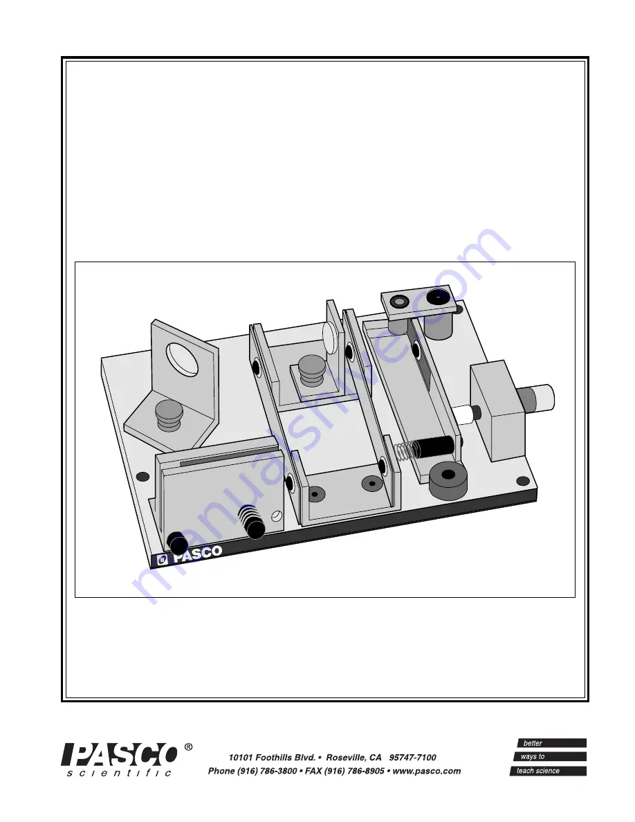
Instruction Manual andExperiment Guide forthe PASCO scientificModel OS-8501
012-02675
10/91
Revision B
Interferometer
scientific
MODEL
OS-8501 INTERFEROMETER
Page 1: ...Copyright February 1986 10 00 Instruction Manual and Experiment Guide for the PASCO scientific Model OS 8501 012 02675 10 91 Revision B Interferometer scientific MODEL OS 8501 INTERFEROMETER...
Page 2: ......
Page 3: ...t Needed Additional Equipment Recommended Theory of Operation 2 Interference Theory The Michelson Interferometer Operation The Interferometer 4 The Movable Mirror 4 Aligning the Interferometer 5 Exp 1...
Page 4: ...amage caused by improper packing of the equipment for return shipment will not be covered by the warranty Shipping costs for returning the equipment after repair will be paid by PASCO scientific Copyr...
Page 5: ...laser We recommend the PASCO 0 5 mW He Ne Laser Model OS 9171 but any low power laser that operates in the visible range will work For optimum ease of alignment the level of the beam should be 1 5 in...
Page 6: ...an interference pattern He allowed a single narrow beam of light to fall on two narrow closely spaced slits Opposite the slits he placed a viewing screen Where the light from the two slits struck the...
Page 7: ...or M2 the path length of one of the beams can be varied Since the beam traverses the path between M2 and the beam splitter twice moving M2 1 4 wavelength nearer the beam splitter will reduce the optic...
Page 8: ...ontrolled and measured using the micrometer knob Each division of the knob corresponds to 1 micrometer 10 6 meter of mirror movement The Movable Mirror To measure the wavelength of light the movement...
Page 9: ...rtical line through the aperture Hold M2 in position and tighten the thumbscrew Rotate the beam splitter so its surface is at an angle approximately 45o with the incident beam from the laser see Figur...
Page 10: ...M1 ALIGNMENT SCREWS LENS 18 mm FOCAL LENGTH LENS HOLDER LASER VIEWING SCREEN 45 M1 ALIGNMENT SCREWS Figure 6 ALIGNING THE LASER SPOTS Figure 7 POSITIONING THE LENS Adjust the Beam Splitter and M1 to s...
Page 11: ...nt in any mechanical system involving reversals in direction of movement By beginning with a full counterclockwise turn and then turning only counterclockwise when counting fringes you can eliminate b...
Page 12: ...Then plug the banana plug of the vacuum chamber into the hole in the interferometer base between the fixed mirror and the beam splitter Adjust the alignment screws of the fixed mirror so the center of...
Page 13: ...auge Of course your room pressure may vary slightly from 76 cm Hg If you have a more accurate way of measuring room pressure you can use that value to replace 76 cm Hg in the above equation Mark a ref...
Page 14: ...difference between these values mi mf is just m the number of fringes you counted as you evacuated the chamber Therefore m 2 d i 2d f However i o ni and f o nf where ni and nf are the initial and fin...
Page 15: ...rs no other maintenance is required If the mylar strip gets damaged or a severe shock causes the interferometer to lose its alignment return the unit to PASCO scientific for repair Replacement Parts T...
Page 16: ...e the interferometer with a spectral or other monochromatic light source Tape two thin pieces of wire or thread to the sur face of the diffuser to form cross hairs Set up the equipment as shown below...
Page 17: ...ting Technical Support Before you call the PASCO Technical Support staff it would be helpful to prepare the following infor mation If your problem is with the PASCO apparatus note Title and model numb...
Page 18: ......