HY13-1526-001-M1/US
Torqmotor™ Service Procedure
TC, TS, TB, TE and TJ Series
Parker Hannifin Corporation
Hydraulic Pump/Motor Division
Greeneville, TN 37745 US
42
Figure 52
Figure 53
Figure 54
Torqmotor™ Assembly
Assemble
end cover
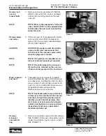
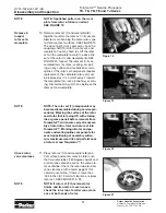
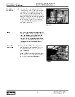
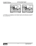
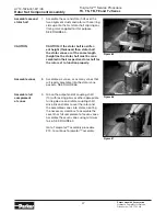
17. Assemble end cover over the alignment
studs and onto the commutator set. SEE
FIGURE 53 & 54. If the end cover has only
5 bolt holes be sure the cover holes are
aligned with the 5 threaded holes in hous-
ing (17). The correct 5 bolt end cover bolt
hole relationship to housing port bosses is
shown in FIGURE 53. After June 2012, end
cover no longer has o-ring section seal.
NOTE
NOTE: If the end cover has a valve (22,
24) or has five bolt holes, use the line you
previously scribed on the cover to radi-
ally align the end cover into its original
position.
Figure 51
Assemble relief
valve parts in
end cover
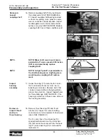
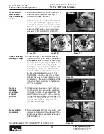
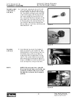
16. If relief valve components items #21, #22
were removed from the end cover (2) as-
semble a
new
o-ring (20) on the two plugs
(21). Assemble a two piece relief valve (22)
in each of the plugs, with the large end of
the conical spring into the plug first and
the small nut of the other valve piece in the
small end of the conical spring. Turn each
of the plug and relief valve assemblies into
the end cover loosely to be torqued later.
3/8 inch Allen or 1 inch Hex socket required.
SEE FIGURE 51 & 52.


