B75 Series 1/4", 3/8", & 1/2" Filter / Regulators
IS-B75
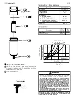
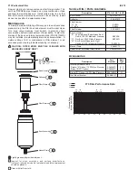
Adjusting Knob
Adjusting Screw Assembly
Bowl Assembly
(Hand Tight)
Inner Valve Assembly
(Disc Assembly) (Poppet)
Adjusting Spring
Bottom Spring
Filter Element
Filter Retainer
Bowl Gasket
Deflector
Diaphragm Assembly
Slip Ring
Regulator Body
(Not Sold Separately)
1/4", 3/8", 1/2"
Spring Cage (Bonnet) Assembly -
Torque: 11.3 to 13.6 Nm
(100 to 120 in. lb.)
Service Kits / Parts Available
Description
R75, 1/4", 3/8", & 1/2"
Adjusting Knob (In Kit CKR75)
R35-0545P
Spring Cage (In Kit CKR75)
R75-0151P
Adjusting Screw Assembly (In Kit CKR75)
SAR55-0532
Adjusting Spring
“A” Range (0 – 25 PSI)
SPR-53
“B” Range (0 – 60 PSI)
SPR-54
“C” Range (0 – 125 PSI)
SPR-55
Slip Ring (In Repair Kit)
R55-0081
Diaphragm Assembly
Relieving (In Kit RKR75)
SAR75-0201
Non-Relieving (In Kit RKR75K)
SAR75-0202
Bowl Gasket (In Bowl Assembly Kit)
GSK-F55-1011
Deflector, Filter Retainer
RKF55
Inner Valve Assembly (In Kit RKR75)
SAR75-0371
Bottom Spring
SPR 391-1
Filter Element
“G” - 5 µ
EK55G
“J” - 40 µ
EK55J
Bowl Assembly
“B” - Polyurethane w Polyethylene Bowl
Guard, 150 PSI Maximum Pressure
BKF55B
“D” - Zinc Bowl, 300 PSI Max. Pressure
BKF55D
“W” - Zinc Bowl w/Wraparound Sight Glass,
250 PSI Maximum Pressure
BKF55W
Repair Kit
Relieving
RKR75
Non-Relieving
RKR75K
Spring Cage Kit
CKR75
Tamperproof (Not Shown)
CKR75T
Accessories
Gauge
0 to 60 PSI (0 to 4 bar)
K4515N18060
0 to 160 PSI (0 to 11 bar)
K4515N18160
Panel Mount Nut *
Acetal Plastic
R05X51
Aluminum
R05X51-A
Wall Mount Bracket
SAR55Y57
Internal Automatic Drain
Plastic (“R” Option, 175 PSI Max. Pressure)
SA602MD
Brass
SA605MD
Brass (W Bowl Only)
SAF105MD
* Requires 1-1/4" hole (1-3/16-18 UNEF-2B)
Installation
All QUBE components are individually tapped (NPT or BSPP) to allow
direct mounting to piping. Also, each FRL component comes equipped
with the necessary screws and O-rings to enable connection to other
QUBE components of the same series without the need for pipe nipples
or special adaptors. Before installing, blow out pipe line to remove scale
and other foreign matter. This unit has DRYSEAL pipe threads; use pipe
compound or tape sparingly to male threads only. Install units in pipeline
so that flow is with the arrows as indicated on the top of the body. Install
as near as possible to equipment serviced.
Reduced Pressure Adjustment
To adjust reduced pressure settings, pull knob out and turn knob
clockwise to increase pressure setting and counter-clockwise to lower
setting. Push knob in to lock adjustment. With relieving-type regulators,
the reduced pressure follows adjustment of the screw. With non-relieving
regulators, adjustment for lower reduced pressure will not be obtained
until the reduced pressure system is “bled-off” or until air flow starts.
Maintenance – Cleaning
Note: To clean, it is not necessary to remove regulator from line. Refer
to drawing as guide in reassembly. If the air supply is kept clean, the
regulator should provide long periods of uninterrupted service. Erratic
regulator operation or loss of regulation is most always due to dirt in
the disc area. To clean, shut off air line pressure and disassemble the
regulator. Refer to drawing as a guide to disassembly and subsequent
reassembly. Clean parts with household soap and blow out body with
compressed air. When reassembling make sure the disc is firmly in place
and that the disc stem fits into the center hole of the diaphragm assembly.
Tighten bowl assembly hand tight.

