background image


Parker EME


Motor/ gear assembly 

23 

192-550002N10 ETH March 2019


Please add the respective safety travels to the mentioned values! 

Stroke, Usable Stroke and Safety Travel: see ETH catalogue 

(solutions.parker.com/ETH_support). 


Sensors and limit switches: see ETH catalogue 

(solutions.parker.com/ETH_support). 


Adjusting the machine reference initiator 

The correct position for the home switch (machine zero switch) depends on the 

application. 

It is recommended to set the machine zero at or near the end of the travel. This 

saves time, as it minimizes the chance that the machine zero is searched for in the 

wrong direction. In some cases it is possible to use one of the limit switches as 

machine zero. This method provides however a reduced precision, as the resulting 

position can normally not be and-linked with the encoder index pulse. 


2.3 

Motor/ gear assembly 

Notes on motor wiring 

In order to adhere to the EMC directive, it is necessary to mount the motor if ever 

possible unchanged. If you require a longer cable, the entire line should be 

replaced with the same or a similar cable. 

If you mount a connector on the new cable, please make sure that the 360° motor 

cable shielding is maintained and that there is no connection to earth via the 

connector housing. 


Improper wiring may lead to severe injuries or death. 

A wiring must always be made from a skilled electrician. 


The motor must be grounded with a separate PE protective lead (green/yellow, 

cross-section at least 2.5 mm

2

).   

This cable must be connected to the available motor-ground connector or - if there 

is non available - with a mounting screw. In the latter case, the coloring under the 

head of the screw must be removed. 


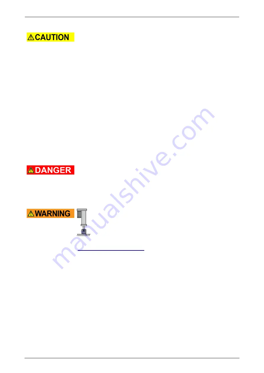
The internal ballscrew is not self-locking! 

Always take care, especially in vertical position of the ETH cylinder that 

the piston rod must be safeguarded!   


In case of non respect severe injuries may occur. 


In this chapter you can read about: 

Motor / gear assembly with inline motor configuration ..................................................... 24 
Motor / gearbox mounting with parallel motor configuration ............................................. 26 
IP65 motor mount ............................................................................................................ 33 


Summary of Contents for ETH Series

Page 1: ...09 38 192 550002N10 ETH March 2019 The data correspond to the current status at the time of printing Mounting instructions ETH Manual Installation Commissioning Maintenance and Repair ETH Electro Cyl...

Page 2: ...2 361081 Fax 39 0 2 36108400 Internet www parker com eme http www parker com eme E mail parker italy parker com mailto parker italy parker com non warranty clause We checked the contents of this publ...

Page 3: ...torques for the mounting of the customer s ETH cylinder 16 2 1 2 3 Accessory mounting bearing block 18 2 1 2 4 Mounting of force sensors 18 2 1 2 5 Mounting Fixing of accessories Rear clevis with for...

Page 4: ...and amount of lubricant 36 3 2 1 Relubrication via central lubrication port standard 37 3 2 2 Relubrication via central lubrication port option 38 3 3 Toothed belt 39 3 3 1 Checking the toothed belt 3...

Page 5: ...uarantee warranty 13 Conditions of utilization 13 1 1 Device assignment This manual is applies for the following devices Electro cylinder for motors and gearboxes ETH032 ETH050 ETH080 ETH100 ETH125 1...

Page 6: ...Introduction ETH Mounting Instructions 6 192 550002N10 ETH March 2019 1 3 Mounting explanation...

Page 7: ...damages caused by applications not in accordance with the intended use of the product 1 5 For Safety Use 1 5 1 General hazards General Hazards on Non Compliance with the Safety Instructions The subsys...

Page 8: ...definition of skilled persons in accordance with VDE015 or IEC364 Persons who have a knowledge of first aid techniques and the local emergency rescue services Persons who have read and will observe th...

Page 9: ...e starting work The manufacturer is unable to accept any liability for damage caused by using non original parts and accessories Safety and protection devices are strictly NOT to be removed or bypasse...

Page 10: ...ift establish an equilibrium and secure the load if necessary Never step under overhead loads danger of being injured Use only transport equipment with sufficient lifting capacity Take care of structu...

Page 11: ...The eye bolts are level and grid with the surface Deformed eye bolts should not be used and screwed anymore Supplied eye bolts are not made of stainless material and must therefore be removed after in...

Page 12: ...llel housing Thread TA on all four sides Thread TB also on the opposite side but not on the underside Unit ETH100 ETH125 inline parallel inline parallel a1 mm 32 32 55 55 a2 mm 32 32 50 50 b1 mm 64 48...

Page 13: ...sed objects in the event of negligent breach of significant contractual obligations Parker Hannifin Manufacturing Germany GmbH Co KG shall also be liable for cases of ordinary negligence however this...

Page 14: ...he ETH cylinder by the customer see page 16 If the motor used with the electro cylinder should be able to exceed individual limit values of the cylinder the respective values for the motor must be lim...

Page 15: ...duct during operation 2 1 Mounting In this chapter you can read about 15 Mounting with mounting threads on the cylinder 15 Mounting with mounting accessories 16 Mounting Instructions 20 Do only use th...

Page 16: ...crews If these specifications are not adhered to the screw joint might fail The failure of screw joint may lead to severe injuries ETH032 ETH050 ETH080 M05 M10 M16 M05 M10 M20 M05 M10 M32 Option F M6...

Page 17: ...w in depth 2 mm For protection classes B and C we recommend for instance a GEOMET coated screw thin layer corrosion protection which must be in strength class 12 9 For the ETH100 125 no GEOMET coated...

Page 18: ...For mounting the force sensor please observe the attached operating instructions respective for the force sensors 2 1 2 5 Mounting Fixing of accessories Rear clevis with force sensor Customer s screw...

Page 19: ...file the lubrication opening in the profile can be concealed by the guide rods Screw together the rod guide module with the screws supplied see Figure 8 Pos 2 and the required tightening torque For ti...

Page 20: ...th an appropriate tool Otherwise the internal anti rotation protection might be damaged Connect the payload always with the end of the thrust rod so that occurring lateral forces are minimized If the...

Page 21: ...remove the groove protection covers Use a sharp screwdriver to lever the ends of the covers off the grooves Pull the entire covers out manually Install the sensors The sensors can be inserted into th...

Page 22: ...rdous area The setting of the end limits depends on the application No sensor is to be mounted in the area of the central lubrication port option The following activation positions at the mechanical e...

Page 23: ...necessary to mount the motor if ever possible unchanged If you require a longer cable the entire line should be replaced with the same or a similar cable If you mount a connector on the new cable plea...

Page 24: ...80 Figure 14 Motor gear assembly ETH032 ETH080 inline ETH100 125 Dismantle motor gearbox Remove motor connector If you use a gearbox we recommend to dismantle the motor from the gearbox first for reas...

Page 25: ...rrs dirt and grease ETH032 ETH050 ETH080 tighten radial clamping screw with tightening torque see Table 1 ETH100 125 Tighten the fixing screws please refer to Figure 17 Pos E2 crosswise with a torque...

Page 26: ...nting with parallel motor configuration With parallel motor configuration increased running noises are possible due to the belt until it has run in In this chapter you can read about Parallel mounting...

Page 27: ...e especially in vertical position of the ETH cylinder that the piston rod must be safeguarded Make sure not to insert your fingers between motor gearbox and electro cylinder We recommend to place a su...

Page 28: ...ease refer to Figure 19 Pos 11 2 3 2 2 Parallel mounting ETH032 ETH080 with Ex Motor Figure 23 Disassembly of an EX motor Figure 24 Flange view Disassembly of an EX motor EX Motor dismantling ETH032 E...

Page 29: ...ift it up to the stop Align the slot of the clamping ring please refer to Figure 23 Pos 1 and the spacer sleeve please refer to Figure 24 Pos 2 to the slot of the hollow shaft Align the hollow shaft s...

Page 30: ...Figure 25 Pos 11 Loosen all tensioning screws of the clamping bushing see Figure 25 Pos 20 approx 3 mm with K1M drive option loosen tensioning element please refer to Figure 26Pos 20a via flange sided...

Page 31: ...tion of the ETH cylinder that the piston rod must be safeguarded Secure motor gearbox against dropping Eye bolts must be used with suitable lifting devices for motors and gearboxes with eyes bolts Ins...

Page 32: ...screws please refer to Figure 19 Pos 11 9 ETH100 125 The ETH100 125 electro cylinder is furnished with tensioned belt When dismantling the gearbox motor the belt must NOT be detensioned Therefore thi...

Page 33: ...see page 30 must be installed In this case the screws Figure 28 Pos7 still have to be loosened easily After the motor gear assembly and before the gradual final tightening of the clamping bushing see...

Page 34: ...nd gear assembly see page 23 Figure 30 Flange prepared for IP65 Apply silicone sealing compound around bores of the parallel housing Mount motor with motor flange to parallel housing see chapter Motor...

Page 35: ...on the operating conditions rotation speed load etc increased surface temperature in the area of the drive may occur When touching it during operation slight injuries from burning may occur Don t tou...

Page 36: ...ming belt is however required Please check the toothed belt for the following aspects Wear at the teeth Cracks in the tooth root surface Fractures in the belt back If you find signs of wear the toothe...

Page 37: ...s used customized version After relubrication a lubricating run must be performed This ensures an even distribution of the lubricating agent Please make sure that the entire length is traveled in both...

Page 38: ...in the mid of the stroke Stroke Stroke limit L2 Lp 2 Stroke Stroke limit L2 stroke 2 Offset Pitch Stroke limit mm Offset mm ETH032 M05 50 15 M10 M16 ETH050 M05 60 15 M10 M20 ETH080 M05 100 20 M10 M32...

Page 39: ...ert the nozzle into the hole in the cylinder profile and place it orthogonally onto the lubricating port Use the defined amount of lubricant see page 36 The amount of lubricant applied can be defined...

Page 40: ...d in the pulley toothing Insert bar please refer to Figure 36 Pos 5 Replace cover please refer to Figure 36 Pos 3 Apply screw lock Wiko 02K43 medium to 4 screws please refer to Figure 36Pos 1 and tigh...

Page 41: ...5 with seal Loosen 4 screws please refer to Figure 38 Pos 8 of the upper bearing flange please refer to Figure 38 Pos 16 do not remove entirely Unscrew 4 screws please refer to Figure 38 Pos 7 and re...

Page 42: ...Pos 8 115 Nm Loctite 242 Wiko02K43 3 4 Belt belt tensions ETH032 ETH050 ETH080 ETH100 ETH1251 ETH1252 Part No 0111 913 0121 913 0131 913 0141 913 02 0151 913 Belt pre tension 210 N 7 N 230 N 7 N 450 N...

Page 43: ...IP65 inline 33 Motor gear assembly 23 Mounting 15 Mounting Fixing of accessories Rear clevis with force sensor 18 Mounting explanation 6 Mounting Instructions 20 Mounting of force sensors 18 Mounting...

Page 44: ...Index ETH Mounting Instructions 44 192 550002N10 ETH March 2019...

Reviews: