


Device
description
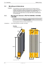
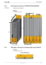
Multi-axis devices
32
192-120148N5 June 2011
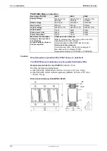
PSUP10: 2400 µF
Maximum capacity in the axis system:
PSUP20 & PSUP30: 5000 µF
100 µF per kW of the temporal medium value of the total power (transmi
power dissipation) in the axis system
Reference value for the required capacity in an axis system
Example: PSUP20 (1175 µF) with one axis controller (440 µF)
Total power 15 kW, 100 µF/kW => 1500 µF required in the axis system.
Axis system: 1615 µF are sufficient.
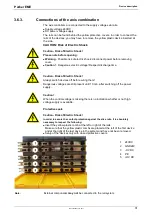
Protective seals
Caution!
The user is responsible for protective covers and/or additional safety measures in
order to prevent damages to persons and electric accidents.
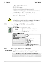
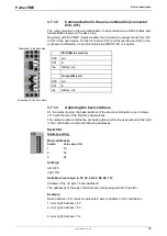
3.6.4.
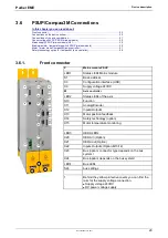
Control voltage 24VDC PSUP (mains module)
Connector X9
Pin Designation
Line cross sections:
minimum: 0.5mm
2
with conductor sleeve
maximum: 6mm
2
with conductor sleeve
(AWG: 20 ... 10)
1
+24 V
2
GND24V
Control voltage 24 VDC PSUP
Device type
PSUP
Voltage range
21 - 27VDC
Ripple
0.5Vpp
Requirement according to safe extra
low voltage (SELV)
yes (class 2 mains module)
Current drain PSUP
PSUP10: 0.2A
PSUP20 / PSUP30: 0.3A
Electric current drain Compax3M
C3M050D6: 0.85
3M100D6: 0.85A
C3M150D6: 0.85A
C3M300D6: 1.0 A
+ Total load of the digital o current for
the motor holding brake
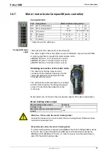
3.6.5.
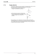
Mains supply PSUP (mains module) X41
By cyclically switching on and off the power voltage, the input current
limitation can be overloaded, which may cause damage to the device.
Wait at least one minute between two switching on processes!
Operation of the PSUP30 only with mains filter!
Device protection


