Parker 8902/EQ Technical Manual Download Page 9

3


8902/EQ HTTL Speed Feedback Option 


Locating 

Holes 

Figure 3  Rear of 

Control Board 

Figure 2  Control board showing 

Option correctly mounted 

Installation 

Fitting the Option 

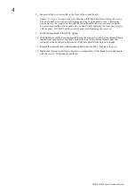
If the option is not factory-fitted, follow the procedure given below. 

WARNING!


Disconnect all sources of 

power before attempting 

installation.  

Caution 

This option contains ESD 

(Electrostatic Discharge) sensitive 

parts. Observe static control 

precautions when handling, 

installing and servicing this option. 

The Control Card assembly needs to be 
removed from the drive as follows to 
fit the Option in “OPTION F” position. 

1.


Undo the two screws securing 
Option A and Option B to the front 
of the drive. If options are not 
fitted, completely remove the 
blank covers for the Option A and 
Option B slots. 

2.


Undo the captive screws (A) 
located in the top and bottom 
handles of the control board. 
Gently pull on the handles to 
withdraw the board from the drive, 
supporting any attached option 
boards. Note that the boards are 
sliding in top and bottom slots. 

3.


If fitted, remove Option A and/or B boards that are 
mounted on the control board by separating the 
connector at the rear of the option board from the 
control board.  

4.


Remove the blanking plate from “OPTION F” location 
(2 screws). 

5.


Remove the terminal block from the HTTL Option. 

6.


Offer up the HTTL Option through the "OPTION F" 
cut-out as shown opposite. Fit the two locating pegs of 
the large connector on the rear edge of the option 
board into the locating holes on the control board, as 
shown opposite. 

7.


Fit the two screws and crinkle washers (C) at the rear 
edge of the Option. 
DO NOT OVERTIGHTEN. 
Tightening torque : 0.2Nm (28 oz-in). 

Ensure locating pegs are correctly located visably 
through locating holes. 

Summary of Contents for 8902/EQ

Page 1: ...echnical Manual aerospace aerospace climate control climate control electromechanical filtration filtration fluid gas handling fluid gas handling hydraulics hydraulics pneumatics pneumatics process co...

Page 2: ......

Page 3: ...ves a division of Parker Hannifin Ltd Although every effort has been taken to ensure the accuracy of this document it may be necessary without notice to make amendments or correct omissions Parker SSD...

Page 4: ...benefit from the equipment Application Area The equipment described is intended for industrial motor speed control Personnel Installation operation and maintenance of the equipment should be carried...

Page 5: ...In particular Stored energy might not discharge to safe levels as quickly as suggested and can still be present even though the drive appears to be switched off The motor s direction of rotation might...

Page 6: ...es 1 Part Number 1 Used On 1 Specifications 1 Recommended Spare Parts 1 DIP Switch Settings 2 Installation 3 Fitting the Option 3 Wiring the System 5 X34 Connections 5 Initial Set up 6 Configuring the...

Page 7: ...sed On This option can be used on 890 drives with the following Product Codes 890SD 890SD Standalone Drive 890CD 890CD Common Bus Drive Refer to the 890 Engineering Reference Manual Appendix E for Pro...

Page 8: ...e a threshold of 3V when using a differential encoder and to 8V when using a single ended encoder Factory default is with all switches set in the ON position 3V 1 2 3 4 ON OFF DIP SWITCH Input Thresho...

Page 9: ...tion B slots 2 Undo the captive screws A located in the top and bottom handles of the control board Gently pull on the handles to withdraw the board from the drive supporting any attached option board...

Page 10: ...ening the front panel screws with the other DO NOT hold the control board while tightening these screws 9 Re fit terminal block to the HTTL Option 10 Refit Options A and B Press the assembly into the...

Page 11: ...the encoder to verify correct operation of the encoder Take special care wiring the encoders to the Option due to the low level of the signals Use twisted pair screened cable preferably with an overa...

Page 12: ...1 Range 1 to 64 This parameter can be used to configure absolute position control applications It must be an integer gear box ratio e g 64 1 If there is a gearbox between the motor and the load set t...

Page 13: ...rt B Clock Dir and Clock Dir Diff direction forward direction reverse assumes ENCODER INVERT is FALSE A wrt A B wrt B Clock and Clock Diff direction forward assumes ENCODER INVERT is FALSE direction f...

Page 14: ...4 01070 279 283 281 Recommended Encoder North America Hollow Shaft Various Bores SSD Drives Part Number Frame Designs TENV TEBC TEFC DD470666 DD470667 DD471123 Hengstler RI 76TD 2048ED 4N20IF Alternat...

Page 15: ......

Page 16: ...er Hannifin Corporation SSD Drives 9225 Forsyth Park Drive Charlotte North Carolina 28273 Tel 1 704 588 3246 Fax 1 704 588 3249 Argentina Australia Austria Bangladesh Belgium Brazil Chile Columbia Cos...

Reviews: