


Bulletin MSG30-3245-INST/UK
Installation Manual
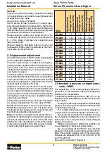
3
Parker Hannifin
Pump & Motor Division Europe
Chemnitz, Germany
Axial Piston Pump
Series PV, series 44 and higher
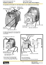
1. Installation and start-up
For a safe and disruption free operation of any
machine or system a careful installation and start
up according to the manufacturers instructions is
mandatory.
Hydraulic systems can be designed for many to-
tally different functions and they require consequently
different start up procedures. The hydraulic pump
is in this respect only one, but nevertheless a very
important component of the whole system.
A general start up instruction therefore can give
many helpful hints but it needs to be completed by
specific additions depending of the individual nature
of the system or power unit.
During installation and start up the following steps
need to be carried out carefully:
Visual inspection
Make sure that all components of the shipment are
complete, free of any damage, free of outside con-
tamination and properly protected against ingression
of contamination.
Cleanliness
Contamination of any kind is the enemy of any hy-
draulic component. It is still the number one cause
for component failure. Therefore
maximum care
and
cleanliness
are required during all handling
and managing of parts that come in contact with
the hydraulic fluid. All ports of the pumps and other
components must be covered until pipes or hoses
are mounted to them. Perform assembly preferrably
in a dry and dust free room. Use only suitable tools.
Installation
Installation horizontal or vertical, avoid rigid connec-
tion from pump to reservoir cover or frame and to inlet
and outlet piping to prevent excitation of the whole
system due to pump vibrations.
Suction port
Position to the side or to the bottom, max. fluid velocity
approx. v = 1.0 m/sec, cut suction pipe inlet under 45°.
Minimum distance from bottom 2 - 3 times diameter
and, even at lowest fluid level, approx. 200 mm below
fluid level. Inlet pressure, even during compensation,
never should drop below 0.8 bar (absolute).
Absolute gas tight connection (risk of cavitation,
noise). Air bubbles due to vacuum in the inlet can
destroy pumps within a short time due to cavitation
erosion. Suction pipe should be as short as possible.
Use only clean, low pressure pipe, avoid sharp el-
bows and any restriction of cross section.
The suction pipe must have access to clean,
cooled and filtered fluid, free of air bubbles. No tur-
bulences or high flow velocities should occur at the
tube inlet. Therefore position inlet as far as possible
away from return line and drain line. Make sure that
the fluid circulation in the reservoir does keep return
flow from suction pipe inlet. In case of positive head
use shut off valve in the inlet, monitored with proximity
switch or equivalent to avoid start up of motor when
valve is closed. When installed into the reservoir use
short suction pipe with pipe end cut under 45°.
Pressure port
Select correct pressure rating for pipe, hose and
connectors. Take pressure peaks into account.
Dimension the piping according to the port size.
Prevent excitation of the system by using flexible
port connections.
Drain port
Always use highest possible drain port of the pump.
Drain port must be higher than pump centerline or
install additional air bleed line. Never combine pump
drain line with other return lines and/or drain lines.
Pump shall not be able to run empty. Max. allowable
case pressure
≤
0.5 bar (2 bar peak), also during
compensation.
Use low pressure pipe/hose, as short as possible
and full cross section according to port dimension.
Do not use elbows or sharp corners. When drain port
is on the side of the pump drain line should have
bridge higher than pump top (also when installed
in reservoir). Drain pipe must end at least 200 mm
below fluid level even at lowest filling level. Never
let drain flow go direct into suction area of reservoir
(temperature, air bubbles). Max. length 2 m, otherwise
use larger pipe diameter than port size.
Note: During operation of PV pumps of all sizes
under the following conditions:
Q ~ Q
max
p
inlet
< 2 bar absolute
P
outlet
< 25 bar
(e. g. low pressure circulation) the drain flow can
change direction. Fluid is taken from the case into
the piston mainly through the decompression orifice
and across the slippers. There is a danger that the
pump case runs dry, the pump overheats and the
bearings lack of lubrication when the fluid is removed
from the pump case.
Therefore the drain pipe must be able to take
fluid from the reservoir. That means: The drain line
must end below fluid level, and a check valve in the
drain line is not permissible. If it has to be installed for
whatever reason the case needs to be flushed with a
flow of 10 - 15% of the nominal pump flow.