background image

-2-

Table of Contents

Important Safety Instructions ........................................................................................ 3

Figure #1 and #2 HCA-806A Front and Rear Panel Drawings ..................................... 4

Introduction ..................................................................................................................... 5

Installing and Rack Mounting Your Amplifier ................................................................ 5

Ventilation Requirements for Your Amplifier ................................................................. 5

Input Connections and Switch Settings for the HCA-806A ......................................... 6

Multi Zone Stereo Operation .......................................................................................... 7

Speaker Connections ...................................................................................................... 7

Mono Bridging ................................................................................................................. 8

AC Power Connections and AC Grounding .................................................................. 8

DC Trigger  Connection .................................................................................................... 8

Operating Your  HCA-806A .............................................................................................. 9

Maintaining Your  Parasound  Amplifier .......................................................................... 9

Fuse .................................................................................................................................. 9

In Case of Trouble ............................................................................................................ 10

Special Features .............................................................................................................. 10

Specifications .................................................................................................................. 11

Parasound Limited Warranty  (USA only) ...................................................................... 13

Summary of Contents for HCA 806A

Page 1: ...g h C u r r e n t M u l t i A m p l i f i e r H C A 8 0 6 A H i g h C u r r e n t M u l t i A m p l i f i e r Current Overload 1 2 3 4 5 6 AC Line Standby Normal O W N E R S M A N U A L HCA 806A Six Channel High Current Power Amplifier ...

Page 2: ...rements for Your Amplifier 5 Input Connections and Switch Settings for the HCA 806A 6 Multi Zone Stereo Operation 7 Speaker Connections 7 Mono Bridging 8 AC Power Connections and AC Grounding 8 DC Trigger Connection 8 Operating Your HCA 806A 9 Maintaining Your Parasound Amplifier 9 Fuse 9 In Case of Trouble 10 Special Features 10 Specifications 11 Parasound Limited Warranty USA only 13 ...

Page 3: ...g This plug will only fit into a grounding power outlet If you are unable to insert the plug into the outlet contact your electrician to replace your obsolete outlet Do not defeat the safety purpose of the grounding plug 11 Power Cord Protection Power supply cords should be routed so that they are not likely to be walked on or pinched by items placed upon or against them 12 Lightning Unplug the un...

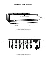
Page 4: ...Mono Bridging Independant Loop 1 2 3 4 On CH 3 Ch 4 Mono Bridging Independant Non Bridgeable Mono Bridging 8 Ω Min Mono Bridging 8 Ω Min Levels Off Loop 1 2 3 4 On Off CH 6 CH 5 CH 4 CH 3 CH 2 CH 1 Main Fuse AC Cord Connector Carry Handle Bridge Switches Input Looping Level Controls Input Connectors DC Trigger GND 12 V 12 Vdc Trigger Connector Power Power Switch Status Indicators EIA Rack Mount Ho...

Page 5: ...nt rack Be sure to use heavy duty mounting bolts to and nylon shoulder washers on both sides of the faceplate to avoid scratching the amplifier s front panel and to help prevent ground loops Contact Middle Atlantic Products at 201 839 1011 to obtain any rack mounting hardware you may need When rack mounting equipment have someone help support the unit while you bolt the component to the rack rails...

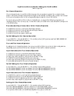
Page 6: ...gurations depending upon your needs Below are examples of four and five channel operation Input Connections for Four Channel Operation Use INPUTS 1 and 2 for your front left and right channels Use INPUTS 3 and 4 bridged mono for your center channel Connect the center output of your processor to INPUT 4 only Use INPUTS 5 and 6 bridged mono for your subwoofer Connect the subwoofer output of your pro...

Page 7: ... the speaker wire will have some sort of mark either printing a raised ridge on the insulation or a different color of conductor This permits you to know which wire you had connected to the and which to the speaker terminals so you can do exactly the same at the power amplifier terminals Polarity is marked separately for both stereo and bridged connections Banana Plugs Banana plugs offer the most ...

Page 8: ...nimum 8 Ω nominal impedance for each speaker connected to bridged channels 3 4 or 5 6 Use of lower impedance at high listening levels may cause overheating or trigger one of the amplifier s protection circuits These restrictions result from the mathematics of the bridging circuitry In the bridge mode each channel of the amplifier functions for only the or half of the musical waveform Thus each cha...

Page 9: ... continues to glow contact your Dealer Installer or Parasound Technical Service for further advice Current Overload LEDs The current overload LEDs for channels 1 through 6 will only illuminate if the unit is driven continuously at or past its maximum current capacity These LEDs will indicate overload of the power supply just before the onset of audible distortion In virtually all imaginable listen...

Page 10: ...out a suitable shipping carton or evidence of improper internal packing will be refused We cannot accept collect shipments After repair under warranty the unit will be returned to you prepaid If we found no problem with the unit we will return the unit with collect charges for return shipping charges Special Features l Massive 1 2 kVA Power Transformer l 90 000 uF Computer grade Capacitors in the ...

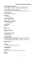
Page 11: ...Total Harmonic Distortion 0 05 at full power 0 02 typical levels IM Distortion 0 03 TIM Unmeasureable Dynamic Headroom 2 dB Interchannel Crosstalk 76 dB at 1 kHz 55 dB at 20 kHz Input Impedances 50 kΩ per channel without looping inputs 1 2 to Ch 3 4 or Ch 5 6 25 kΩ per channel if looping inputs 1 2 to either Ch 3 4 or Ch 5 6 17 kΩ per channel if looping inputs 1 2 to both Ch 3 4 and Ch 5 6 Input S...

Page 12: ...warranty This warranty becomes void if the product has been damaged by alteration misuse accident or neglect Alteration includes any removal obscuration or defacement of its serial number This warranty becomes void if unit has been connected or operated contrary to printed instructions The warrantor assumes no liability for property damage or any other incidental or consequential damage whatsoever...

Reviews: