


About the Model 7976 Standalone Termination Unit
1-4
7976-A2-GB20-10
August 1998
Front Panel LED Status Indicators
Figure 1-2 shows the front panel of the Model 7976 Standalone Termination Unit.
For more information on front panel LEDs, refer to Chapter 4,
Monitoring the Unit
.
PO
WER
ALARM TEST
DSL
G.703
98-16003
7976 M/SDSL
TM
TM
Figure 1-2.
Hotwire Model 7976 Standalone Termination Unit Front Panel
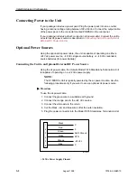
Rear Panel Interface Connections
Figure 1-3 shows the physical interfaces of the Model 7976 Standalone
Termination Unit.
POWER
DSL
COM
TX
RX
G.703
75
Ω
120
Ω
98-16005
O
I
Figure 1-3.
Hotwire Model 7976 Standalone Termination Unit Rear Panel
Summary of Contents for Hotwire 7976
Page 56: ...Monitoring the Unit 4 14 7976 A2 GB20 10 August 1998 This page intentionally left blank...
Page 66: ...Testing 5 10 7976 A2 GB20 10 August 1998 This page intentionally left blank...
Page 78: ...Security 7 6 7976 A2 GB20 10 August 1998 This page intentionally left blank...
Page 104: ...Standards Compliance for SNMP Traps B 6 7976 A2 GB20 10 August 1998...
Page 112: ...Technical Specifications D 2 7976 A2 GB20 10 August 1998...